Technology spotlight: digital optical comparator
VISIONx has launched a patent pending technology that it says is a better way to verify that manufactured parts match up with their CAD data. The company explains the merits in this special product spotlight.
Optical comparators, also referred to as profile or contour projectors, were first introduced in the 1940s and are still used in a range of industries to verify that manufactured parts are within tolerance. These instruments are well suited for use on the shop floor as well as in the metrology and quality control labs because they are versatile, easy to use and robust. They also deal well with complex geometries (i.e. shapes not easily described by simple elements like lines and circles) and, up until now, they have been the easiest way to quickly compare a part to its drawing to allow the operator to make an overall Pass/Fail determination.
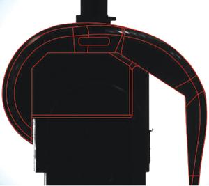
The overlay of a knee implant CAD drawing onto the live video image of the part.
And while optical comparators are considered to be a cost effective measuring tool, it is also widely recognized that they rely on old technology and suffer from a number of shortcomings. The most important is the need to use an overlay, also called a template or a Mylar. With traditional optical comparators, the part’s drawing is scaled to match the comparator’s optical magnification and printed on a transparent overlay. This overlay is then placed on top of the comparator’s screen and aligned with the image of the part. The operator can then ascertain if the part is within tolerance. There are many problems related to the use of these overlays, including the following:
• The cost of the overlays;
• The cost and maintenance of the equipment required to print the overlays;
• The cost and maintenance of the equipment required to calibrate the overlays;
• The time required to print the overlays;
• The time required to calibrate the overlays(and verify this calibration);
• Using overlays necessarily introduces an error when printing the part’s drawing onto the overlay (no printer is perfect);
• Overlays can tear, get damaged, stained and worn;
• Overlays need to be physically stored and retrieved, taking time and storage space;
• There is a risk that the operator may select the wrong overlay;
• Overlays can be used by only one person at a time;
• If you want your suppliers to verify with an overlay the parts that they are sending you, you need to physically send it to him, which results in costs and delays;
• Setting up overlays on a comparator is a slow and operator-intensive process;
• It’s impossible to “recall settings” for an overlay (i.e. position and orientation). The operator needs to realign every time that he sets up a part.
VISIONx has recently developed its patent pending VisionGauge digital optical comparator which solves all of these problems and many others as well.
This new instrument uses a high resolution digital camera and a low distortion telecentric lens to capture a high resolution and geometrically exact image of the part. The software that is at the heart of this instrument then projects this image, along
with the part’s CAD overlay, onto a high resolution quad monitor display. This approach produces images with an on-screen resolution better than that of traditional 30 in. optical comparators. It also allows for a number of benefits over traditional optical comparators.
• It produces a very high contrast image so that there is no problem viewing it in full daylight.
• It is much more accurate than traditional optical comparators.
• It can carry out automatic Pass/Fail determinations, completely eliminating operator subjectivity and error.
• It can automatically send measurements and data to a spreadsheet, text file, or a database.
• It allows the user to be more productive and get more work done with a single machine.
• It works directly with the CAD data so that no overlays, templates, or Mylars are required.
• It can be used to collect images (either with or without the CAD data overlay and with or without annotations), measurements and data.
• It can also carry out automated measurements (like a video CMM).
• It has a smaller footprint and uses less floor space than a traditional optical comparator.
• It can be moved more easily and without requiring re-calibration (i.e. “rolling cart” configuration is standard).
• It has a much greater depth of field, i.e. “everything is in focus all at once.”
• It has a longer working distance so there is more clearance between he lethe part and tns.
• It allows you to compare a part to its CAD data beyond the optical field-of-view (because the CAD data tracks the part and follows the stage motion).
• It has LED illumination for stable illumination over a 10 year life. This means that there are no more bulbs to change.
This instrument is the ideal tool when you need to compare a part to its CAD drawing. It is appropriate for a wide range of industries including orthopedics, medical device manufacturing, automotive, aerospace, energy, and precision mechanical components and assemblies. It is also appropriate for higher magnification and high accuracy applications such as Micro Electro-Mechanical Systems (MEMS) device manufacturing, electronics and semiconductor.
Early adopters include the orthopedics, automotive and aerospace industries, among others. In the orthopedics industry, 100 per cent of parts must be inspected and compared to their CAD data during the manufacturing process, directly on the shop floor. These are implants with complex geometries and tight tolerances. In this application, the digital optical comparator’s higher accuracy provides an obvious benefit.
Also, because parts can be made in small batches, there is a constant need to change the overlay. With traditional optical comparators, this involves removing the overlay, walking over to the overlay storage area, finding the correct overlay, walking back to the machine and positioning the overlay. All of these operations can easily take a few minutes. With the digital optical comparator, the operator only needs to scan in the work order’s barcode or press a button on the screen to automatically call up the correct overlay, which comes up already correctly positioned over the image of the part. The productivity gains are immediate and all possible errors are eliminated.
In the automotive industry, this instrument is used to check flexible parts, among other things. Comparing flexible parts, such as door and window trim, to their CAD data is notoriously difficult and the digital optical comparator’s ability to quickly and easily align the part and the drawing using an intuitive three axis three speed joystick makes the job much simpler. In the aerospace industry, customers are checking critical areas such as the fir tree on engine blades.
Like traditional optical comparators, this one uses collimated back illumination to produce clear and crisp images with sharp edge profiles. However, while traditional optical comparators typically use halogen bulbs that need to be replaced on a regular basis, this new instrument uses up-to-date LED technology that provides stable illumination over a ten year life. As is the case with traditional optical comparators, front illumination is also available (to carry out surface inspection, for example).
There are two main reasons why the digital optical comparator is more accurate than traditional optical comparators. The first has to do with the size of the lens.
As with all things manufactured, it is impossible to produce a perfect lens and all lenses have defects and imperfections, to a certain degree.
Furthermore, the difficulty in producing a lens increases rapidly with the size of the lens. Traditional optical comparators need to use large lenses to project the image of the part onto their 30 in. screen. The optical comparator only needs to project the image of the part onto the camera’s sensor, which measures slightly less than one inch. This lens can be manufactured much more accurately and the raw image that is projected onto the camera sensor of the instrument is thus more geometrically accurate than the image projected onto the 30 in. screen of a traditional optical comparator.
The instrument’s camera produces a digital image that is sent to the system’s on-board computer. The software can then carry out further corrections on this image to eliminate the last minute geometric distortions and inaccuracies. And this is the second reason for this new system’s increased accuracy: the optical comparator carries out mathematical corrections to the image to make it virtually perfect. Overall, this new instrument is roughly 10 times more accurate than traditional optical comparators. The use of a small camera sensor, instead of a large 30 in. projection area, is also at the root of the instrument’s superior optical properties: a much greater depth of field and a longer working distance. It is also the principal reason why these systems have a much smaller footprint and use up less manufacturing floor space than traditional optical comparators. And, of course, because this new instrument works with a digital image, it is able to carry out fully automated measurements, with sub-pixel accuracy, just like a video CMM. The digital image can also be saved to disk, either with or without the CAD data overlay and with or without annotations, along with measurements, annotations and other data.
Another significant benefit to this approach is the fact that the comparator can compare a part to its CAD drawing beyond the optical file of view. With traditional optical comparators, the overlay is fixed on the screen and doesn’t move when the stage carrying the part moves. But with the new comparator, the overlay “tracks the part.” This means that if you have a part that is larger than the field of view, you can move the stage to see another portion of the part and the overlay will follow the stage. The CAD drawing moves with the part.
And because these systems are completely software-driven, it is possible to automate all of the operations. As a result, it is possible to operate this new system using only a barcode reader and a joystick. This results in significant productivity gains. Users typically report a doubling of their productivity with this instrument, i.e. they can get twice as much work done with a single machine.
The new optical comparator is an easy-to-use system for the shop floor and the metrology lab. It is available in horizontal and vertical configurations and with industry-standard 5X, 10X, 20X, 50X and 100X magnifications. This new instrument brings optical comparators into the 21st century. It uses advanced technology to offer a better solution to the classic manufacturing problem of ensuring that parts match up with their CAD drawing. QC
Patrick Beauchemin, P.Eng. Ph.D. is with VISIONx Inc., Pointe Claire, QC.
Methods Machine Tool Inc., Sudbury, MA, is the North American distributor for the VisionGauge digital optical comparators.
subscribe now


Keep up to date with the latest news, events, and technology for all things metal from our pair of monthly magazines written specifically for Canadian manufacturers!
Start Your Free Subscription- Stay connected from anywhere

Easily access valuable industry resources now with full access to the digital edition of Canadian Metalworking.

Easily access valuable industry resources now with full access to the digital edition of Canadian Fabricating & Welding.