


Application/Sales Engineer
Cooling and lubricating coolants can reduce the temperature of the material being cut and improve chip removal.
Editor’s Note: This article was developed from information presented during the Horn Technology Days 2017 event held at Paul Horn GmbH in Tübingen, Germany, May 10-12.
Grooving and parting-off applications present unique challenges. Unlike a longitudinal turning application that allows chips to move in three directions without restrictions, during grooving and parting-off processes you are machining between flanks, which confine chip movement to just two directions.
Consider two key points to avoid problems. One is chip forming and the other is chip control. Good chip forming ensures that the material is plastically deformed by the tooling so the chips are narrower than the width of the cutting insert to avoid damage to the groove flanks. An example is a 5-mm-wide groove insert that creates a chip that is 4.85 mm wide.
Chip control ensures that chips will not cause problems during the machining process. The goal is to produce short helical, spiral, comma, or tear chips (shaped like 6s and 9s). These types of chips are more likely to provide stability in the grooving and parting-off process.
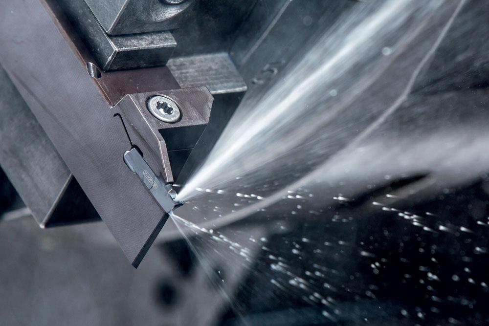
Cooling lubricants and cutting fluids can dramatically affect the reliability of grooving and parting-off processes. When applied correctly, cooling lubricants can reduce the temperature of the material being machined and improve chip removal. Keep in mind that no matter how much coolant is poured on an application, or how effective the coolant is, it will have little to no effect if it is not applied to the cutting edge.
Coolant can be supplied by an external or internal means. When external coolant is supplied via nozzles spraying on the toolholders, only a small amount of the coolant actually gets to the cutting edge so it has less of an effect on the cutting application than coolant delivered using a through-coolant toolholder delivery system. This is especially true when machining deep grooves and working with materials that are easily work-hardened, such as superalloys and stainless steels.
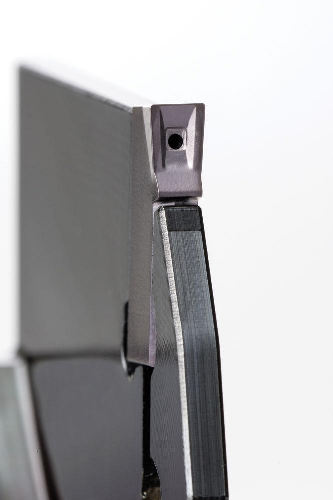
When internal coolant is supplied directly through the toolholder, it is directed precisely to the cutting edge, enabling a much more reliable process. Internal coolant, or through-coolant, holders are available in many variations. Some direct the coolant to immediately above the insert, some to immediately below.
Coolant from above can greatly improve chip control, which is a key to longer tool life. It can also reduce built-up edges (BUE).
Coolant supplied below the cutting edge will reduce the cutting zone temperature while minimizing flank wear. This also aids in chip removal. Reducing the temperature makes it possible to use tougher varieties of inserts while maintaining tool life and cutting parameters or, in some cases, increasing tool life and improving process reliability. This process also delivers the best results when engagement times are long and temperature is a limiting factor.
Through-coolant holders eliminate the need to adjust coolant lines and always direct the coolant to the tool’s cutting edge. External coolant lines can be bumped out of alignment while operators are changing tools or loading parts, which can cause process variation or premature tool failure.
Coolant applied through the toolholder is precisely directed to the cutting edge, where it will have the most impact on the cutting process.
We can’t talk about coolant delivery without talking about coolant pressure. With the right coolant pressure it is possible to influence chip formation in grooving and parting off. Coolant pressure as low as 5 bar (72 PSI) can start to reduce crater wear. As the pressure increases to 20 bar (290 PSI), it can reduce BUE. Coolant pressure of 40 bar (580 PSI) can influence chip control and direction. High pressure application of 80 bar (1,160 PSI) or more can aide in chipbreaking.
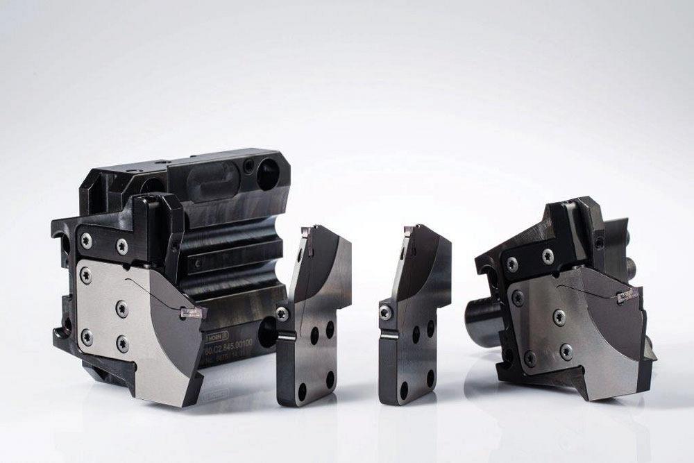
Turning application technology has come a long way from the time when you simply clamped a piece of tool steel in place for a turning application. Today the flexibility, simplicity, increased stability or rigidity, and improved accuracy are making modular grooving systems popular.
New modular tools make it possible to produce assemblies that are tailored for specific applications while being made up of completely standard components. This can reduce the need for special tools. These systems provide a stable structure, while their modular design gives you flexibility and a large variety of tool configuration options.
The pre-plumbed systems simply bolt on to accommodate many coolant delivery options that offer quick changeover without the need to hook up coolant lines. Many of the modular systems also allow for center height adjustability that can be especially helpful when cutting difficult materials. A large number of combinations are possible with a relatively small number of components, which enables standard tool systems to be used throughout an entire production process regardless of the machine interface.
So what about cam machines that are 20 or 30 years old or older? Truth is, many companies still run older cam-style machines, and these machines aren’t being ignored. There are new options for them too.
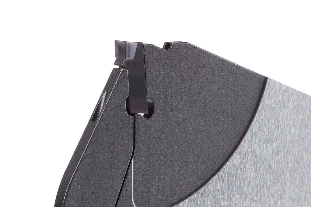
The P-style blades have many options with indexable blades that are designed to fit in existing tool blocks. Solid-carbide options allow for direct replacement of these blades for groove and cutoff applications.
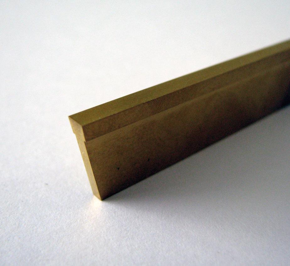
Materials are changing, and they are generally not getting easier to machine. Challenging materials such as heat-resistant superalloys, stainless steels, and lead-free alloys such as brass pose new challenges that demand modern machining strategies.
Let’s use a lead-free brass alloy as an example of a challenging material. Brass is known for its good machinability properties. A leaded, free-machining brass is particularly popular in the production of turned parts. Tools used to machine free-machining brass have a negative chipping angle that produces small, short chips. With new laws that regulate the use of hazardous materials such as lead, new grades of lead-free brass have emerged that require a change in machining processes.
The negative chip angle that works so well in free-machining brass does not work nearly the same in the lead-free version. Machining trials have shown that lead-free brass is best machined with geometries more suited for steel. For the best process capability it is important to apply the correct geometries and grades for the material you are machining. Not all brass is the same.
It is important to consider the economics of parting off. Since parting off is often the final operation in manufacturing a component, reliability is crucial.
New tooling options are available for P-style blade users.
The narrowest indexable inserts should be used in the parting-off process as this can factor into significant material cost savings. These savings multiply exponentially when you are machining alloys that have a substantially higher material cost, such as high-temp superalloys.
Ken Hamming is application/sales engineer at Horn USA Inc., 888-818-4676, www.hornusa.com.


Keep up to date with the latest news, events, and technology for all things metal from our pair of monthly magazines written specifically for Canadian manufacturers!
Start Your Free Subscription
Easily access valuable industry resources now with full access to the digital edition of Canadian Metalworking.

Easily access valuable industry resources now with full access to the digital edition of Canadian Fabricating & Welding.


