New Takes on Press Brake Tooling
How OEMs are changing tooling and setup for today’s shop
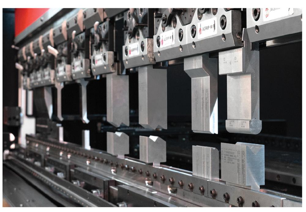
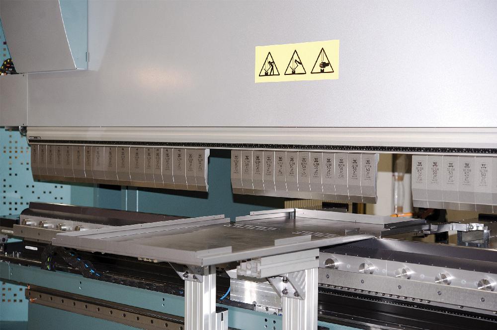
Fixed height tooling paired with common shut height dies can produce multiple bends with one setup. Photo courtesy of Amada.
Press brakes are core pieces of equipment in any fabricating shop. The equipment, the tooling, and the basic process have been well-established for production runs for decades. But the shift to small batches or even single-piece flow and the desire to produce more complex shapes using press brakes have kept new designs and capabilities flowing from the OEMs.
Tooling--and the brake’s interaction with tooling--is expanding equipment capabilities and making single-part bending economically feasible.Here are some tooling thoughts and offerings from brake manufacturers.
Amada
Scott Bowerman, National Tooling Sales Manager
Amada has been working on systems to help fabricators reduce setup time and minimize production time through stage bending. Amada fixed height (AFH) tooling paired with common shut height (CSH) dies provides the ability to produce multiple types of bends that require various tooling types with only one setup.
All of the AFH tooling has the same overall punch height so operators can place a combination of different punch profiles across the brake in one setup. A single 1-V die provides clearance around the die, which accommodates both small-part flange lengths and additional part flange relief.With the CSH die system, 90-degree bends, 30-degree bends, offset bends, flattening operations, and various inside-radius bends can be produced in one setup. All tools have the same shut height, so any punch and die combination can be placed in the brake without worry of crashing a tool.
Bystronic Inc.
Frank Arteaga, Head of Product Marketing
Bystronic has created a self-contained, automated tool changing system built around its Xpert press brakes, designed to automate and speed the setups for efficiently producing small batch sizes.
The main element of the system is a compact robotic tool changer that positions tool sets, up to V80, in the clamping systems of the upper and lower beams. The 6-axis robotic arm retrieves and replaces tools in the tool magazine, which is also located within the machine. Tool segment changes take 10 seconds. Tool storage capacity is up to 90 ft. of dies and up to 30 ft. of punches. The tooling can be used in manual or robotic setups and represents only a slightly higher cost than standard tooling.The upper tools can also be rotated 180 degrees and inserted into the beam for added versatility.
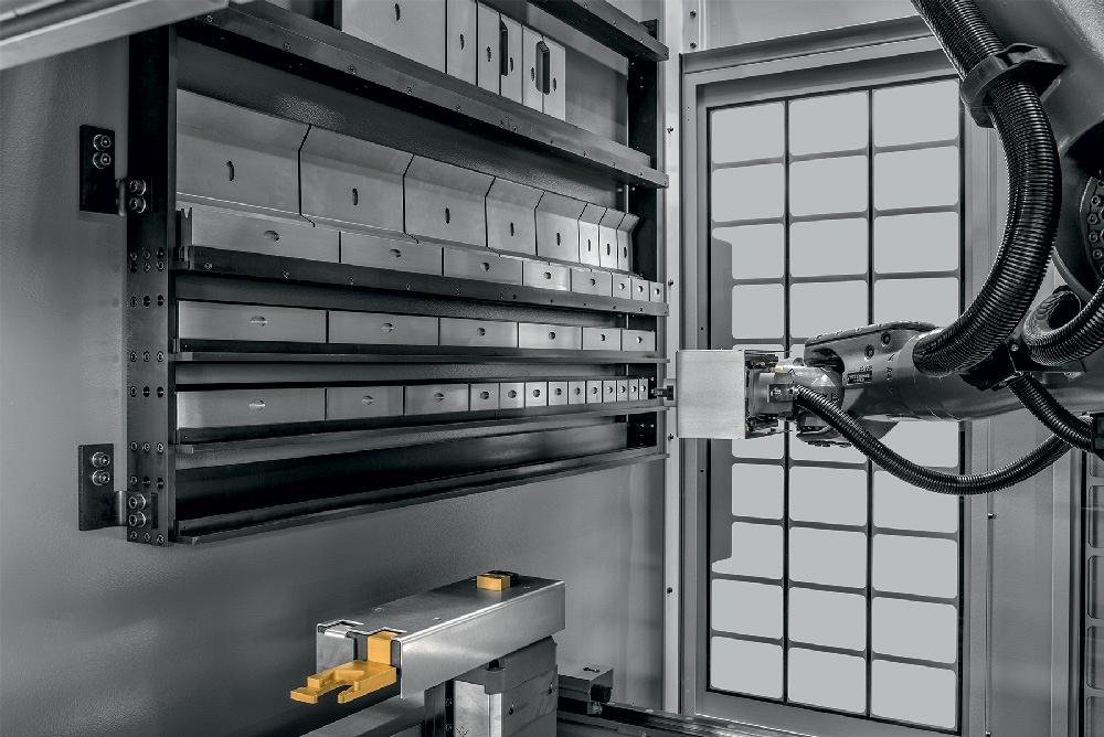
A compact robotic tool changer positions tool sets up to V80 in the clamping systems of the upper and lower beams. Photo courtesy of Bystronic Inc.
Sensor technology detects new tools and integrates them into the tool magazine and verifies that tools are properly seated.The Xpert Tool Changer system is equipped with a cleaning nozzle that cleans the whole length of the bending table using compressed air prior to inserting new tools.
MC Machinery Systems
Casey Schlachter, National Sales Manager
The biggest thing right now is the devices—robots and other tool-changing devices. By robots I mean a 5-axis articulated robot moving the tools in and out of the machine without an operator. The intent is to change the tools faster without human intervention and mistakes.We’ve developed another tool to help operators who do change the tooling. The Videre system, that’s Latin for vision, projects the setup information onto the ram to show the operator where the tools should go. It projects the tool name and tool profile, showing the shape and height of the tool to be loaded and simultaneously shows the proper visual and numeric position for the tool to scale. The operator can choose the tool that matches the image and put it in place under the image. This same projection system displays the part being bent on the ram, also in real time. This larger image illuminates right in front of the operator and is much easier to see than an image off to the side on a control screen.
Our machine also has a process that helps an operator be sure he has the right tool and die in place. Once the upper and lower tools are in place, the software directs the brake to bring the tools to a shut position with 2 tons of pressure or less—not enough pressure to damage the tools. If the shut height registers within a few thousandths of what is expected for the tooling, it verifies that the correct tools have been loaded and the ram goes up to allow the forming process to begin.
Salvagnini America
Bill Bossard, President
Our strategy and thought process is to devise and build a press brake with a tool set that can be rearranged within six to eight seconds. We’re headed down the road in terms of tool adjustments as opposed to tool changing. Our automatic tool adjustment (ATA) simply rearranges the tooling to correspond to the particular length necessary.
Segmented punches--in lengths that have been thought out to cover any formed dimension from 2 in. up--are set up. Segmented dies, exactly equal to the punch segments, are also set up so both the punches and dies can be adjusted for the bends required by a series of individual parts.
The ATA can be paired with a tool set changer (TSC) to save more time when tooling needs to be changed, for example, from a straight punch to a gooseneck punch or from one V-die opening to another.
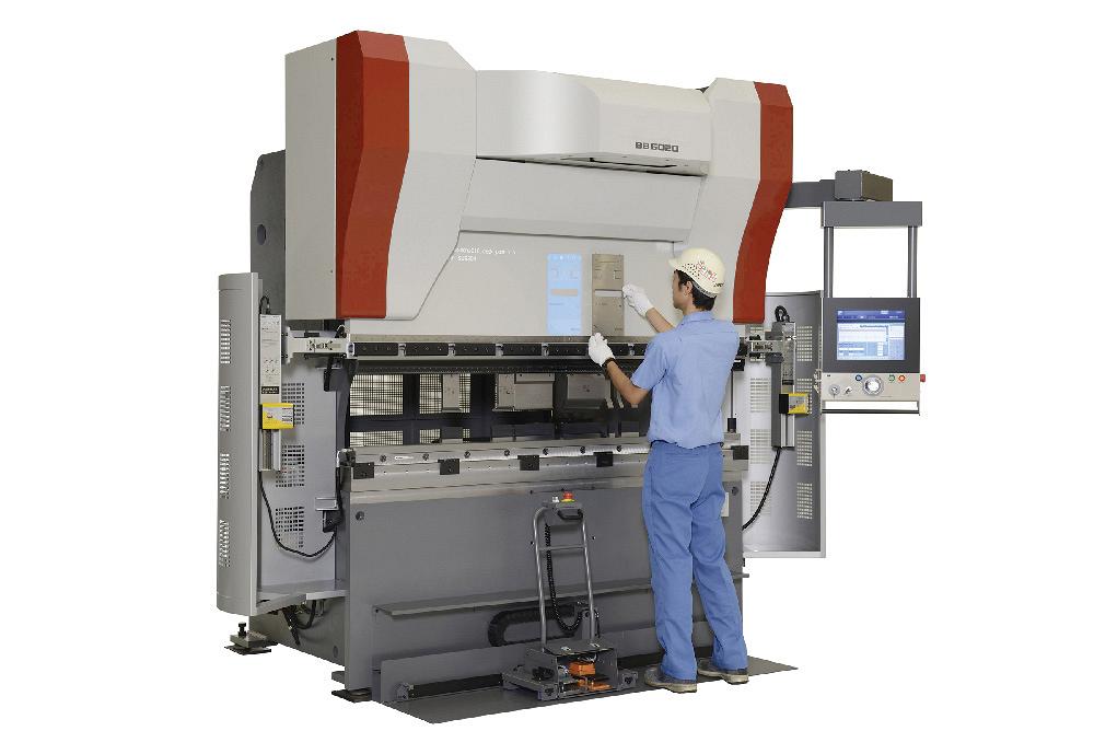
The Videre system projects setup information onto the ram to show where tools should be positioned. Photo courtesy of MC Machinery Systems.
TRUMPF
Tom Bailey, TruBend Product Manager
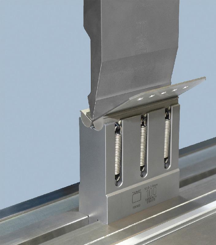
Although mechanical tooling is a fairly established innovation for press brakes, its cost slowed down its adoption. Now, more manufacturers are getting into complex designs, and that is pushing them to invest more in tooling. Rather than using lower dies made of hard pieces of metal, these tools articulate in some way to allow high-quality, aesthetic bends on complex geometries. They may be spring-loaded or have cams to allow for the more complex bends.
With the mechanical die there is no gap below the material. It is supported against the moving surface during bending so there is no empty space for the material to flow into.
For example, the RollBend tools have a cam at the top of the lower die so it looks like a flat piece of steel rather than the V-shaped die before you start rolling. When you make the bend, the set of cams in the punch roll up and support the material during the forming. Flange length limitations become a lot smaller, and it helps with bending features that would normally distort, such as cutouts and tapered flanges. Bends of 180 degrees up to 40 degrees are possible.
Amada, 847-466-2000, www.amada.com
Bystronic Inc., 847-214-0300, www.bystronicusa.com
MC Machinery Systems Inc., 630-616-5920, www.mcmachinery.com
Salvagnini America, 513-874-8284, www.salvagnini.com
TRUMPF Inc., 860-255-6000, www.us.trumpf.com

subscribe now


Keep up to date with the latest news, events, and technology for all things metal from our pair of monthly magazines written specifically for Canadian manufacturers!
Start Your Free Subscription- Stay connected from anywhere

Easily access valuable industry resources now with full access to the digital edition of Canadian Metalworking.

Easily access valuable industry resources now with full access to the digital edition of Canadian Fabricating & Welding.
- Trending Articles
1
CWB Group launches full-cycle assessment and training program
2
Achieving success with mechanized plasma cutting
3
3D laser tube cutting system available in 3, 4, or 5 kW
4
Brushless copper tubing cutter adjusts to ODs up to 2-1/8 in.

5
Welding system features four advanced MIG/MAG WeldModes