


Present Parts!
Robots, lasers, and data sources combine for quick, accurate parts marking
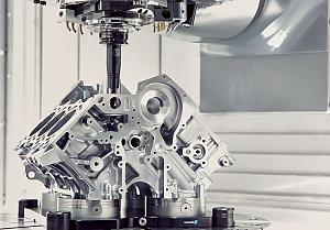
Laser heads can be mounted on a robot to take the marking to the part rather than the part to the laser marker. Photo courtesy of TRUMPF.
Almost every part manufactured today must be traceable. From a large part assembled into a defence product to the smallest of bone screws used to put people back together, components need to be identified.
An identifier added to a product at the end of the line might be required to show the who, what, where, and when of a part’s production to record the batch and/or add a unique code that isn’t shared by any other part. Or a component might need an intra-factory identifier used to follow its progress through production.
Robotic laser marking can be programmed to place identifiers on thousands of like parts as they move through a production line or use predefined programs to automatically recognize and accommodate part differences in a make-to-order environment.
End-of-arm grippers can be programmed to swap out as needed to present individual parts or trays of parts to the laser. A robot often can grab and load small parts easier than human fingers, particularly when the hand is wearing a glove to avoid transmitting dirt to the parts.
Whatever the identifying need, robotic laser marking is up to the task for inline production or as a stand-alone process.
Part ID and Size Flexibility
“One obvious benefit of using laser marking paired with robotics is the elimination of hard tooling,” said Dave Girardot, product line manager for the tools division of North America, Coherent Rofin. “With a robot you can pick up a part, find it with vision, and position the part under the laser head. It gives you an abundance of flexibility on placing and positioning, and it is easier, quicker, and cheaper than hard tooling scenarios.”
The flexibility of robotic laser marking allows programming that will handle a family of parts that come in various sizes and configurations. You still need some repetition to make the process worth the investment, but it is becoming easier and more cost-effective to use robotic laser marking for batches that don’t number in the thousands.
Girardot said, “For example, we can look at parts A1 which are being presented by the robot, pull up the laser marking program, and mark them. Then the robot can change gripper if needed, present parts A4 which are identified by vision, and the laser can use the program specific to that part for its appropriate marking. And so on.
“We are seeing the automotive and medical industries really throwing JIT production scenarios into a more accelerated, compact format. Instead of lots of 5,000 or 10,000 parts, an order might be for 200 parts. This demands the capability to do more on-the-fly process changes without having to do hard marking tool swaps.”
The only limitation, he said, may be in positioning tolerances. “Most applications robots provide adequate positioning tolerance of about 0.0015 in. We’ve worked with parts the size of a thumb tack and smaller. But some higher-level applications get down to the micron level with tolerances of ± 1 µm. You can’t achieve that with the robots by themselves.
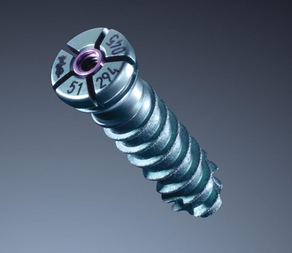
Robots present a tray of small medical parts like bone screws to a laser marker to receive unique device identifiers, permanent identifiers required by industry regulations. Photo courtesy of TRUMPF.
“There are other means of part presentation guidance to assist when a robot is put in the micro position. A vision system can look at a small part, and the robot can offset the part based on the vision feedback. That process may require additional vision, hardware, and programming, and in some cases, some type of hard tooling will be needed to process at that tight of a tolerance.”
When several parts are positioned in a tray for marking, the robot may be able to present one tray, and while those parts are being marked, load the next tray to keep the process going. A vision system might be part of the system to verify orientation of the parts in the tray.
Equipment and Data Communications
Vision technology and robotic handling can be located at nearly any point along a production line to enable marking on-the-fly (MOF). A robotic conveyance system can be located under the laser to rapidly lift a part or tray of small parts for marking without slowing the overall process.
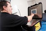
Salay Quaranta, business development manager for TruMark at TRUMPF North America, said, “Laser marking combined with robotics can be accomplished at an extremely high rate. You are providing great throughput and production efficiency without the need to have any human interaction to present the part to the laser.”
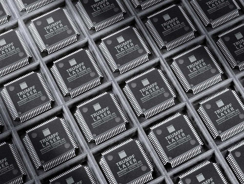
The laser markers tend to have remote control interfaces such as digital I/Os, Ethernet or EtherCAT®, PROFIBUS® or PROFINET®, Serial RS-232, or a TCP/IP. Quaranta said, “This allows for communication from a master control to command the laser to start marking when the robot has placed the part. We have a lot of customer requests to also query from a database via interconnectivity platforms to laser mark production or product-specific information such as unique device identification (UDI). This type of system is usually developed with the understanding that it is part of a high-production environment because we are communicating a lot of data.
“For high workpiece throughput we have a dual-head marking laser. It allows the laser to be split 50/50 to concurrently mark two parts with identifiers or for sequential marking.”
More than marking can occur when a robot presents a part, said Quaranta. “The marking system can be used for some non-traditional processes such as surface texturing or cleaning. For example, this has been done by some automotive customers to prepare a surface for the next step along the production line such as robotic welding.”
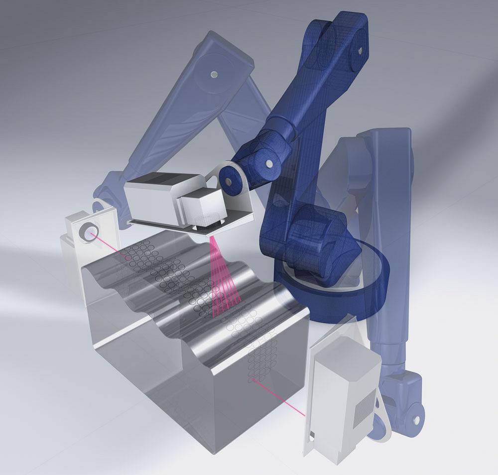
For some applications, an integration designer will suggest mounting the laser processing head on a robot that will bring the marking to the part rather than the part to the laser. This works well for large parts that are difficult to move.
“There are times that it’s not practical to move a part or it’s very time-consuming to move it multiple times. This is where robotics and conveyance systems are great to facilitate laser marking,” said Quaranta.
When it comes to positioning large parts for marking, Girardot said, “There is usually a maximum size that a robot can handle. That is specified by its lifting capacity. A robot will also have a G-load rating that needs to be observed so it doesn’t quickly swing a large part around and lose control or lose gripping ability.”
Small parts can be grouped in a tray to be presented to the robot for laser marking. Photo courtesy of TRUMPF.
Quaranta encourages companies to involve the laser manufacturer in the early stages of a robotic marking design process. “If they are working towards a robotic setup, the laser manufacturer can provide guidance as to what platforms are available, what interfaces may be necessary, how to integrate the laser, and how to care for the complete automated laser marking system.”
Coherent Rofin, 408-764-4983, www.rofin.com
TRUMPF Inc., 860-255-6000, www.trumpf.com

subscribe now


Keep up to date with the latest news, events, and technology for all things metal from our pair of monthly magazines written specifically for Canadian manufacturers!
Start Your Free Subscription- Stay connected from anywhere

Easily access valuable industry resources now with full access to the digital edition of Canadian Metalworking.

Easily access valuable industry resources now with full access to the digital edition of Canadian Fabricating & Welding.
- Trending Articles
1
Class is in session for college connections
2
BlueForge Alliance partners with Nuts, Bolts & Thingamajigs to develop Submarine Manufacturing Camps

3
Engine-driven welding machines include integrated air compressors
4
Orbital tube welding webinar to be held April 23

5
Portable system becomes hot tech in heat treatment