


More Feed More of the Time
High-feed turning reduces cycle time by increasing metal removal rate
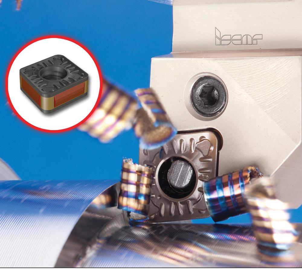
High-feed turning creates wide chips that are easily evacuated from the cutting zone. Photo courtesy of Iscar Tools.
There are many ways to measure productivity, including spindle utilization and parts per shift, but to get an idea of how effectively your parts are being produced, it’s good to know your Q (material removal) rates.
A quick calculation — Q = 12 x ap x f x Vc — gives you the cubic inches of material that are being removed per minute. This rate affects cycle time and can be a good indicator of productivity.
To increase material removal rates, one or more variables must be changed. In high-feed turning, for example, the cutting depth is reduced but the feed rate is increased.
A high-feed insert’s cutting edge geometry and chipbreakers enable better chip thinning, and these tools produce a wide, thin chip that contributes to good chip control. These turning tools also can significantly reduce cycle time by running at feeds up to eight times higher than conventional turning tools.
“Like most types of machining, high-feed turning is all about creating a balance among the cutting data,” explained Steve Geisel, senior product manager for Iscar Tools. “For example, in a high-feed turning operation, the depth of cut [DOC] will have to be smaller because you can’t have both a high feed rate and a high DOC. It simply doesn’t work.”
A typical turning operation in carbon steel could have the following cutting data:
DOC = 0.250 in.
Feed = 0.020 in. per revolution
The Q rate for this type of cut is much lower than the high feed rate option. When a high-feed tool is used, better material removal rates will be achieved.
When the DOC is reduced to 0.080 in. but the feed rate is increased to 0.120 in./rev., assuming a consistent spindle speed, the Q rate is nearly doubled. This means that the volume of chips removed from the part is doubled in the same amount of time.
“The math is there,” said Geisel. “The math supports taking shallow depths of cut at much higher feed rates.”
However, a high level of productivity—as measured by material removal—can be achieved only by using the optimal tooling with the appropriate machining strategy. Inserts designed for high-feed cutting must be used, and the tool and part must be held securely.
“These tools move very quickly, and operators need to be aware of the increased speed,” said Geisel. “Before the e-stop could be hit, it’s possible that the tool could collide with the part or even the chuck.”
Increased Pressure
A high-feed turning operation creates a lot of tool pressure. When this pressure increases, the machine, toolholding, and workholding must all be able to handle it. The part itself also needs to be able to support high-feed turning. Thin-walled or delicate parts typically are not candidates for this type of turning.
Using a steadyrest and having the part supported with a live center are two options that can help improve stability in the cut.
Implementing efficient machining strategies also will contribute to the reduction of cutting forces by distributing the forces effectively, eliminating vibration, facilitating chip evacuation, are ultimately leading to a higher volume of metal removal.
A higher Q rate by definition means that more chips will be produced in a shorter amount of time; fortunately, high-feed turning typically produces a chip that leaves the work zone easily.
“Typically a wider chip is produced because of the increased feed rates in comparison to normal turning,” said Chad Miller, product manager for turning and advanced materials for Seco Tools. “The upside to a thicker chip is that it is easier to break. We see a real advantage when machining gummy materials with high-feed inserts because the chipbreaking capabilities are greatly increased.”
The downside to high-feed inserts is that more contact area is created between the insert and the workpiece.
“This large contact area [is what increases] the load and tool pressure,” said Miller. “The machine and workpiece setup have to be rigid in order to gain the maximum benefit out of high-feed inserts.”
Even though chips are spread out over a longer area on the insert, chip control is good, with small chips that break easily being produced.
“The chipbreakers on the inserts are specifically designed to work at these angles and feed rates,” said Geisel. “In fact, the entire insert, from the carbide grade, coating, insert geometry, and chip former, has been designed just for this type of work.”
Typically, a hard substrate is used for a high-feed turning insert. In an ordinary turning application, the nose of the insert takes most of the punishment. In high-feed turning, though, the chip is spread out over more area, meaning that the strongest part of the insert takes the abuse. For this reason, a hard, thick-coated insert is the norm.
“You don’t need a substrate that is as tough when you are performing high-feed turning, but the design of the insert does matter,” said Geisel. “The placement of the chipbreaker on the insert and how the insert is held in the toolholder are both very important.”
Iscar’s high-feed turning line uses dovetail pocketing to ensure a tight fit in the holder.
“We even use the word dove in the name of our line of tools because of the dovetail pocketing,” said Geisel. “While this isn’t new technology, it is important in this type of turning because a dovetail pocket is a very strong pocket.”
When a dovetail pocket is used, all of the cutting forces are forced into the toolholder and the setup doesn’t rely on the insert’s screw or clamp to provide support. It becomes a very rigid setup because more material holds the insert in place.
In addition, because the cutting forces are being directed back into the entire length of the toolholder, large top clamps or screws that hold the insert in place no longer need to be as large.
“In some setups we can even eliminate any holding device that goes on top of the insert,” said Geisel. “When you put a clamp on top of an insert, you are creating an obstruction, which keeps chips from getting out of the cutting zone and keeps coolant from getting in. Unobstructed chip flow is what we try to achieve.”
subscribe now


Keep up to date with the latest news, events, and technology for all things metal from our pair of monthly magazines written specifically for Canadian manufacturers!
Start Your Free Subscription- Stay connected from anywhere

Easily access valuable industry resources now with full access to the digital edition of Canadian Metalworking.

Easily access valuable industry resources now with full access to the digital edition of Canadian Fabricating & Welding.
- Trending Articles