Editor
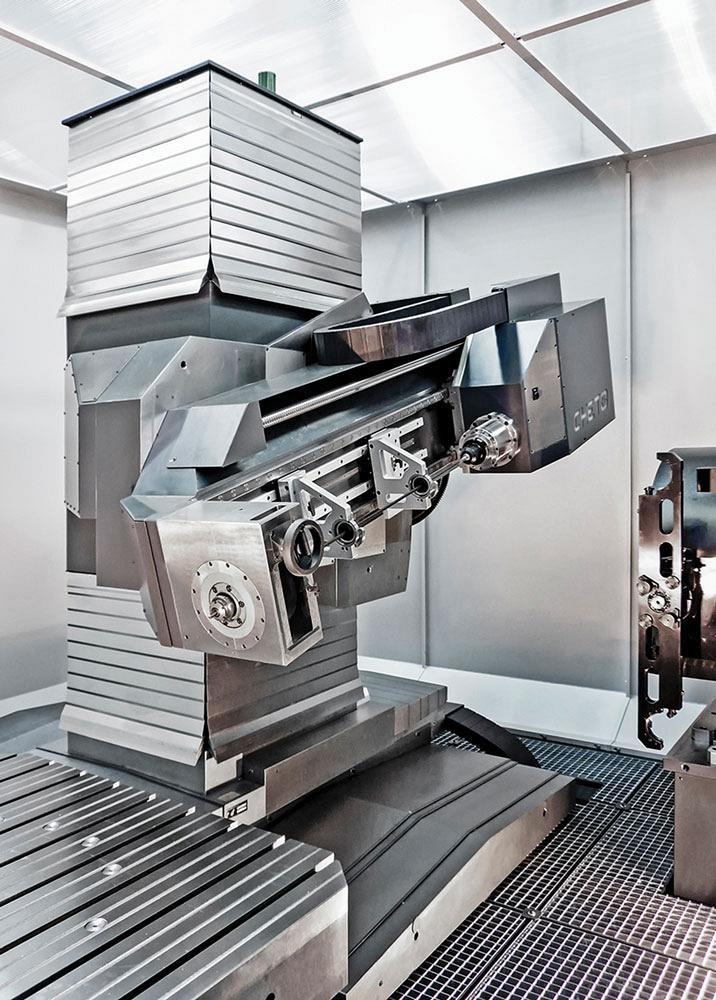
Deep-hole drilling machines, such as those manufactured by Cheto, are one option for creating deep, straight, round holes. Photo courtesy of Elliott Matsuura Canada.
Editor’s Note: This article is based on Cheto Corp. Chief Technology Officer Sergio Andre’s presentation at the International Manufacturing Technology Show (IMTS), Sept. 12-17, 2016, Chicago.
In drilling it’s all about the hole and, more specifically, the parameters of the hole.
Straightness, cylindricity, and concentricity all need to be accurately maintained to create a high-quality hole. These factors also are affected by drift, runout, and circular runout, which compromise hole quality.
Round holes are the easiest type of hole to produce, and can be created using any number of methods, the most popular of which is obviously drilling. Creating square, ovular, or other complicated shapes can be accomplished by using milling and EDM processes.
Inclined holes, through holes, and blind holes all create problems that must be solved by the tool being used and with the correct cutting parameters. All of this needs to be correct to get the hole you want to the depth you want.
And, the deeper the hole, the more difficult creating it becomes.
Deep-hole drilling typically is described as holemaking to length-to-diameter ratios that are higher than 10xD.
It is a process that can be used with several types of materials, including ferrous and nonferrous.
Producing a deep hole with a good finish, accurate diameter, and straightness control is the goal of deep-hole drilling. Hole quality is key to the development of high-quality products.
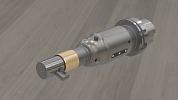
The aerospace, automotive, oil and gas, hydraulics, maritime, medical, and mouldmaking industries all require deep hole drilling. Sometimes specialty tools need to be employed to help ensure hole quality (see Figure 1).
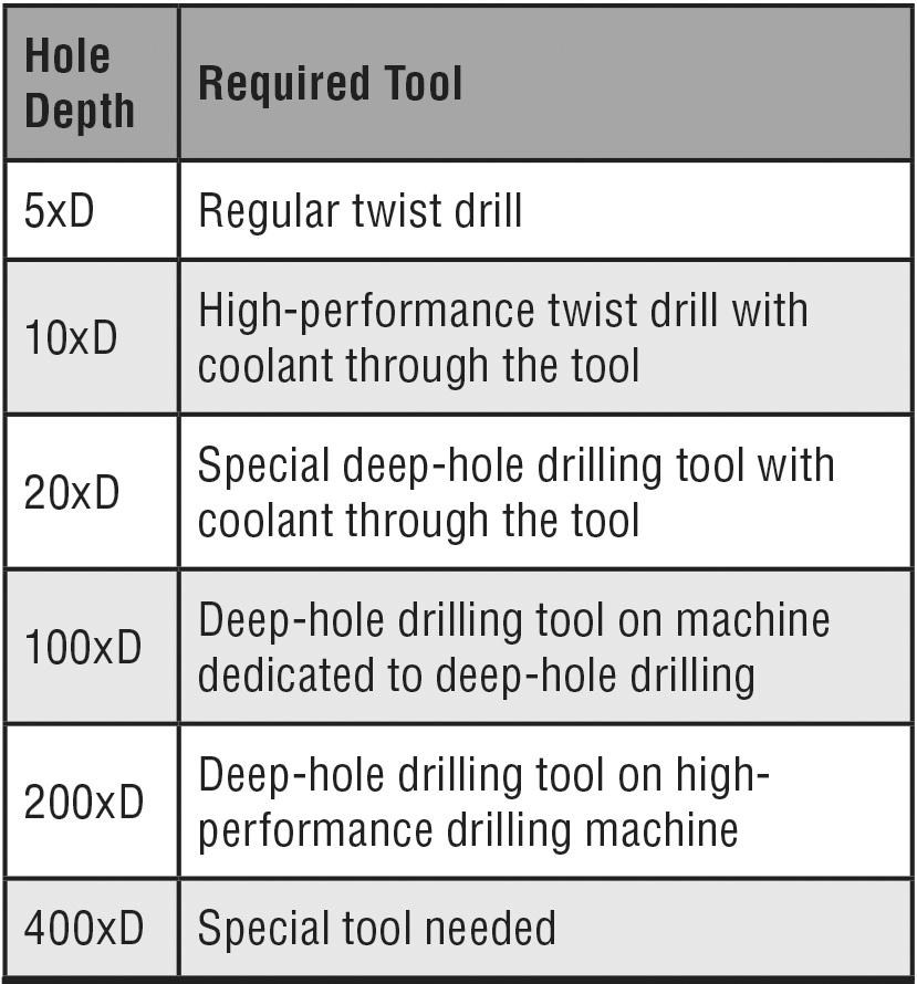
Figure 1
Following are three common ways to drill holes, and the process you select depends on the type of part being produced and the type of hole being drilled.
1. Tool rotation and stationary part. This type of drilling typically is used on nonsymmetrical parts or on round parts that require out-of-centre drilling. In this case, cutting speed is determined by tool rotation speed. It must be noted that the occurrence of drift can be higher than with other processes.
2. Part rotation and stationary tool. This type of drilling is commonly used for round parts with deep, centred holes. Cutting speed is determined by tool diameter plus part rotation. Drift in this type of drilling is less compared to the tool rotation method.
3. Tool rotation and contrary part rotation. Drilling when both the tool and the part are rotating is a method used for round parts that need deep, centred holes. Cutting speed is determined by tool diameter plus the tool rotation plus part rotation. Drift in this method is lower compared to the other two processes.
The deeper a hole gets, the more chance there is for the drill to drift, especially if the tool encounters intersections with other holes or part features. The amount of drift varies depending on the type of drilling operation being performed. Tool rotation (X), part rotation (Y), and tool rotation and contrary part rotation (Z) all produce different drift (see Figure 2).
In all cases, the chance for drifting is reduced if a pilot hole is used. According to Cheto Corp. Chief Technology Officer Sergio Andre, the angular alignment of the pilot hole is key, and care must be taken when a pilot hole meets an intersection.
Feed rate and other cutting parameters also affect drift, and, of course, different materials require different parameters.
Less than 70 years ago, the meaning of deep-hole drilling was automatically connected to gundrilling. There simply weren’t any other methods. Today, with advances in mechanical technology, more methods are available that enable deep-hole drilling. The three most common are the gundrill, single tube system (STS), and ejector system.
As its name implies, the gundrill initially was developed to drill gun tubes. It is a machine dedicated to creating long, straight holes with relatively small diameters, and it can be used on several types of material.
The tools for this machine typically incorporate a single-edged head and V-shaped flute. The drill body is slightly thinner than normal to allow the chips and coolant to exit. Today some gundrills have a carbide head and some use indexable inserts.
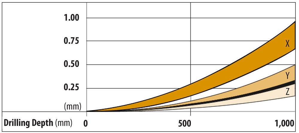
Figure 2 -- The data in the chart is based on information from single-flute gundrill-makers at optimal conditions. Chart courtesy of Cheto Corp.
Coolant is fed through the coolant hole in the tool from the spindle to the edge of the tool. A gundrill also can be used in a conventional drilling centre machine, but it requires high coolant pressure.
It is possible to create small holes (those with diameters between 0.5 and 3 mm) with a gundrill given the appropriate tool and setup. Hole diameters between 3 and 50 mm are the normal range for gundrilling, but holes of 50 to 75 mm also are possible, but gundrilling in this range is less productive than hole production on an STS machine.
When you use a gundrill with indexable inserts, feeds 40 per cent higher than with a traditional gundrill can be achieved. Combined with the quick replacement of inserts and reduced storage needs, a gundrill with inserts can reduce setup time, production time, and overhead. However, the initial cost is higher.
When you are drilling with a drill bush or making a pilot hole, you must start penetration without rotation at a slow rotation (less than 50 RPM). Then the coolant and the spindle can start working. A similar method is used when the desired depth is reached. The coolant should be turned off and the gundrill removed with the spindle stopped or in slow rotation (less than 50 RPM).
The recommended coolant type for deep-hole drilling process with a gundrill is oil. Viscosity should be around 8 to 10 mm2/s at 40 degrees C for diameters between 0.5 and 1.5 mm. Oil viscosity should be around 10 to 15 mm2/s at 40 degrees C for diameters greater than 1.5 mm.
It is possible to use emulsion, but the feed must be reduced to 60 to 80 per cent of what is possible when using oil. When using an emulsion, however, coolant pressure can be reduced to 20 per cent. It is paramount that pressure and flow are adequate to remove chips efficiently.
Single tube systems (STS) employ coolant that is fed through the exterior of the tool. Seals are needed to ensure coolant reaches the cutting area and the tool’s edge has an opening to extract coolant and chips from the head to the chip box.
This type of system can’t be used with small-diameter tools. Most tools for STS machines have a minimum diameter of around 15 mm. However, it can be used to create holes up to 300 mm in diameter.
Because an STS machine has high productivity, it should be considered first for batch production. It can be run using higher feeds than the gundrill, and the edge of the tool can perform several different operations, including drilling, machining, polishing, and trepanning.
The same tool can be used with different inserts on the cutting edge to improve productivity and increase the number of operations.
Some disadvantages come along with an STS setup, however.
It takes a while to change out a tool and aligning the tools can be a complicated task. Usually the tools used in these machines are not sharpened, so they become more expensive to use.
It is critical that the chips are broken into small enough pieces that there is no chip congestion in the flute. It also is necessary that high coolant flow is used. This requires a high-capacity tank, coolant filtration, and high-pressure pumps.
This type of system is like an STS, but the coolant is fed differently because the flute has two tubes. The external tube pumps coolant to the edge of the tool, and the interior tube allows for the exit of coolant and chips. These systems also are commonly called double tube systems (DTS).
Ejector systems require even more coolant pressure than STS machines. They also are more prone to congestion caused by failure to successfully expel chips.
Like the STS machines, ejector systems have high levels of productivity. The same tool also can use different kinds inserts on the cutting edge. With this system, however, it is not necessary to change the entire tool; just the head can be changed.
A drawback of these machines is that they cannot be used for holes with diameters less than 20 mm. Also, proper chip creation and coolant pressure are important so that the return tube does not get clogged.
Editor Joe Thompson can be reached at jthompson@canadianmetalworking.com.
Cheto Corp. courtesy of Elliott Matsuura Canada, 905-829-2211, www.elliottmachinery.com.


Keep up to date with the latest news, events, and technology for all things metal from our pair of monthly magazines written specifically for Canadian manufacturers!
Start Your Free Subscription
Easily access valuable industry resources now with full access to the digital edition of Canadian Metalworking.

Easily access valuable industry resources now with full access to the digital edition of Canadian Fabricating & Welding.