Product Technical Specialist
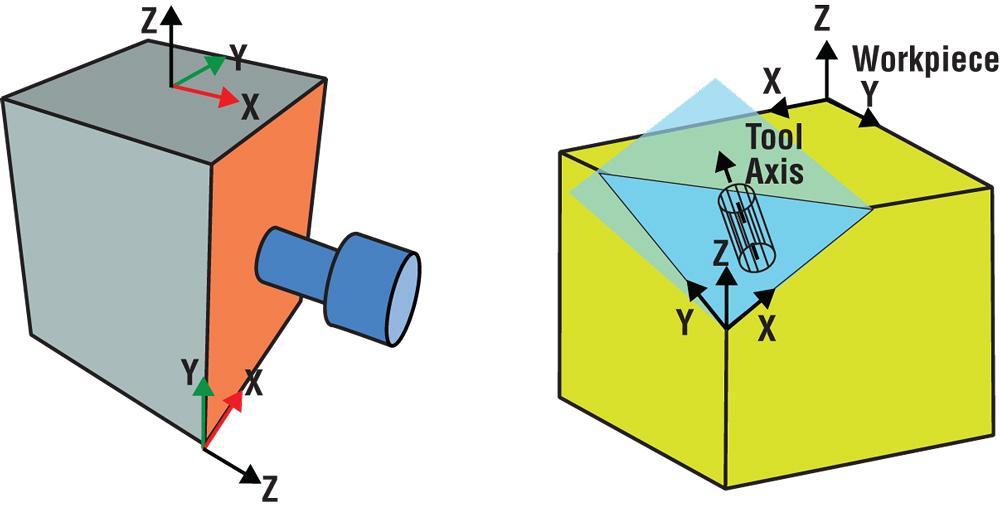
Figure 1.
CNC technology continues to accelerate. It’s difficult to figure out what matters and what doesn’t when it comes to new features and new processes. Technology surrounding 5-axis machining can be even more difficult to digest, especially if you don’t yet have a 5-axis machining centre.
It also takes time to distill the massive amounts of technological jargon and explain software features resident in a 5-axis machining centre’s control that make the process more efficient. It can be illustrated, however, why shops all over the country are investing in 5-axis to increase profit margins on parts they previously were producing on 3-axis machines.
Common problems do arise with the process, but resolutions have been designed to solve them. Here are just a few.
Even an uncomplicated part that is 5-sided requires multiple part-zero setups. In these situations, you waste time and compromise accuracy when you have to continuously flip the part to machine each side. Doing the same part using a true 5-sided process turns five setups into one.
A software feature for transforming the plane (see Figure 1) simplifies 5-sided programming and eliminates the hassle of setting up part-zero five separate times. The technology does the work so you can start making chips. You just need to locate one part-zero, and the remaining part-zero locations can be defined as incremental measurements from the original location.
Additionally, you can still program the geometry on each of the sides if you’re programming in an X/Y plane. The transform plane function basically changes programming on a 5-axis mill back to 2.5-D programming that you would do on a 3-axis mill, which means that you don’t need to worry about the tilting or rotating.
How it works: The tool axis becomes the Z axis, and the control calculates all of the required tilting and rotating.
Each time you refixture, you waste valuable time re-entering the distance from part-zero to the centrelines of rotation and then reposting the program.
If your control has a software feature such as tool centre point management, you post the program once and machine the part, no matter where it is in relation to the centrelines of rotation on the machine.
Tool centre point management solves the problem for CAM software. The CAM programmer generates the toolpath based on the part model’s zero location and, therefore, you can post the program independent of where the stock is fixtured on the table. This is a substantial time-saver for a 5-axis part.
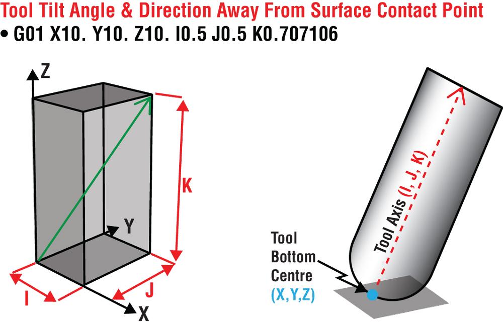
Figure 2.
Benefits include a faster setup, less complex post-processing, and time saving reposting the program.
How it works: The machine coordinates are uncoupled from the part coordinates, which means you only need to find the top corner of the part and the machine knows where the machine position is located in relation to the centrelines of rotation.
CAM systems generally use tool vectors to generate the toolpath. To make programs independent of the machine’s rotary configuration and to simplify the post-processor, a tool vector input control software feature for 5-axis machining centres is available (see Figure 2).
The tool vector input feature lets you specify the tool tip location relative to the workpiece and the tool axis vector instead of using address letters to specify the B- and C-axis angles.
Executing the program is much faster because the post doesn’t need the machine configuration and the centreline of the rotary axes. Tool vector input allows the control to compute machine angles and positions, and calculates the angle the tool is going to tilt from the contact point of the surface.
Benefits of this feature include scheduling flexibility (because the program can run on another 5-axis machine with a different axis configuration), it simplifies post-processing, and the control computes machine angles and positions.
How it works: Because CAM systems generally use tool vectors to generate the tool path internally, this feature allows the machining centre’s control to accept the vector code so the CAM system doesn’t have to filter the code through a post-processor.
The control lets you specify the tool tip location relative to the workpiece and the tool axis vector instead of using address letters to specify the A-, B-, and C-axis angles. The control’s software automatically compensates for the position of the tool using part coordinates that are relative to the centrelines of rotation for the B and C axes.
Therefore, the control understands where the workpiece is located relative to the centrelines of rotation of the rotary axis.
Simultaneous 5-axis toolpaths can result in odd looping rotary moves that leave marks on the part when the program is interpolated by the machine’s control.
A feature called toolpath linearization, which is specific to 5-axis, G-code (NC) programs, eliminates the many line segments in the form of XYZBC or AC moves that a CAM system uses.
The results of using this feature are improved surface finish quality, smaller NC programs, and the elimination of workpiece gouging.
How it works: The tool tip and tool vector are interpolated between tool positions with respect to the workpiece, even with the tool and part rotating inside the machine. The tool tip basically attaches itself to the workpiece instead of blindly following the commanded rotations.
For 3-D surfaces, you cut off of the tool centreline to get a better surface finish. Oftentimes you are forced to repost the program because you need to adjust the tool diameter for wear.
By using 3-D tool compensation, you eliminate the need to repost the program to adjust the tool diameter to compensate for tool wear or tool substitution.
In addition to compensating for tool wear, this feature eliminates idle time caused by tool breakage, and it saves time compared to rewriting the program to adjust for tool wear, tool breakage, and tool substitution and then reposting the program.
How it works: The 3-D tool compensation feature adds UVW, which is the surface contact point where the radius comes in contact with the surface it is cutting. You only need to change the diameter (D) and radius (R) values of the tool. The 3-D tool compensation feature does the rest.


Keep up to date with the latest news, events, and technology for all things metal from our pair of monthly magazines written specifically for Canadian manufacturers!
Start Your Free Subscription
Easily access valuable industry resources now with full access to the digital edition of Canadian Metalworking.

Easily access valuable industry resources now with full access to the digital edition of Canadian Fabricating & Welding.