


Job Shops Face the Challenge of Mixed Production
Find the balance between material removal, process security
Because mixed-production machine shops face the daily uncertainty of not knowing what jobs will come through the door next, having an optimized tool for each component feature is unfeasible.
Instead, machine shops require a set of tools that allow them to produce whatever components are needed.
How do you decide what this tool set is to get started on the right foot with any job? Having mixed production can mean making some compromises. Finding a balance is the key.
Having a dedicated tool for the operation gives you the opportunity to optimize job but it is not always possible. Consider the following points to help get you the best start possible:
Toolholding. Quality toolholding provides you with minimal runout and optimum rigidity. This is critical for any tool. Runout at the cutting edge reduces tool life, has a negative effect on productivity, and causes poor surface finish.
Grades. CVD coatings tend to be thicker than PVD coatings, providing better protection against heat in large arcs of engagement. These thick coatings tend to round off cutting edges, however, and the tool is therefore not as sharp. For low arcs of engagement in which sharp edges are required, the thinner PVD coatings keep the edge prep closer to being as sharp as it was intended to be.
Geometries. Choosing insert geometry suitable for the material you are cutting also can have a big impact on process security and productivity. Inserts are sold either direct-pressed or ground. Both work well in many areas, so it is best to consult with your local technical sales representative to optimize your needs.
Insert seating. Clean pockets with air at every index to remove debris that can cause poor seating of the insert. Always be sure to load the inserts with matching corners. Use lubricant or antiseize on all screw threads and faces.
Process security. Use a wrench capable of providing the correct torque to the screw. This gives the best pre-load designed for the screw and prevents over- or under-tightening. Both can lead to movement of the insert and breakage.
Speed and feed. Understanding the material composition that you are cutting is critical to knowing the speed at which you will be able to run. Make sure to use the materials guide in the back of the catalog and reference the right composition and hardness. You can then reference the grade you chose and determine a starting speed for the tool.
Feed rates based on chip thickness, also known as hex, for a given geometry are the best way to calculate table feed. Referenced in the cutting data section of the catalog are all of the tool concepts and geometries. Each geometry has an optimized chip thickness relative to all materials. Once you know that, you can calculate the feed per tooth (fz) based on lead angle and arc of engagement.
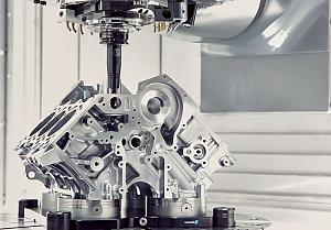
Milling Application
Shoulder and face milling. When the objective is to produce flat faces and square shoulders, you need to consider arc of engagement on the wall to set the correct feed rate. If your tool engagement is less than 25 per cent of the tool diameter, you need to increase the feed rate to bring back the chip thickness. If you don’t do this, your chip could be too thin. This can cause rubbing, which will leave a poor surface finish and decrease tool life.
Ramping. When you choose a ramp tool path, consider the type of feature you want to create and keep in mind the ramp angle allowed (RPMX). Again, consulting the catalog is a good idea. Guessing at any stage of circular ramping from solid, or ramping beyond a tool’s capability, can have catastrophic results.
Plunging. Plunging can provide you with high metal removal rates with long overhangs. With square shoulder tools, never exceed the parallel land known as the bs of the insert. When retracting the tool, it is better to move it off the wall so it does not drag during retraction.
Slot milling. This offers a set of different challenges, including chip evacuation and vibration. Indeed, these issues are exacerbated when you are milling with large engagements because vibration often accelerates tool wear. In these situations, light cutting geometry in combination with a cutter with optimized differential pitch can take care of this issue and create a low-vibration milling process.
Brian MacNeil is milling products and application specialist, Sandvik Coromant Canada, 905-826-8900, www.sandvik.coromant.com.
subscribe now


Keep up to date with the latest news, events, and technology for all things metal from our pair of monthly magazines written specifically for Canadian manufacturers!
Start Your Free SubscriptionAbout the Author
About the Publication

- Stay connected from anywhere

Easily access valuable industry resources now with full access to the digital edition of Canadian Metalworking.

Easily access valuable industry resources now with full access to the digital edition of Canadian Fabricating & Welding.