Automation Manager
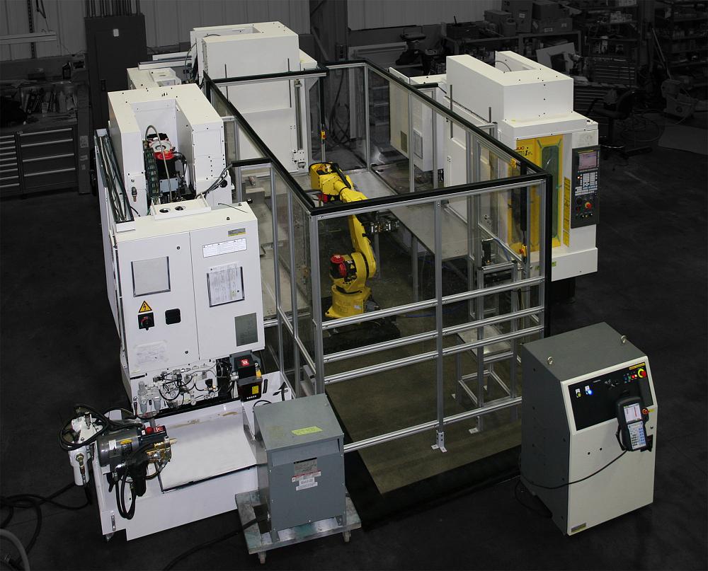
Basic automation cells comprise a single machine and a single robot, but in this example, three machines are being tended by a single robot.
Looking at trade magazines or attending a tradeshow, you might notice that everyone seems to be talking about automation.
Years ago automation was something that only the automotive companies or shops with substantial production could afford. The automation technology that’s available today, however, is affordable enough for more shops to consider, and it’s flexible enough to be effective for smaller lot sizes.
But where should a beginner start?
Understanding basic automation concepts allows you to better evaluate you shop’s own needs and understand the decisions that need to be made when you are considering automation on a machine tool. While we will focus on cells that are based on an articulating robot, the concepts can be applied to other forms of automation as well.
Basic Cell Configuration
Basic automation cells comprise a single machine and a single robot, but in reality there are no limits. One, two, or even 20 machines and many robots can all be part of an automation cell.
While there are no standard configurations, basic cells tend to be similar. The primary components are the machine tool, robot, end-of-arm tooling (EOAT), electrical interface between the robot and machine, infeed/outfeed system, and guarding.
Cell Requirements
Understanding what you want a cell to do is very important.
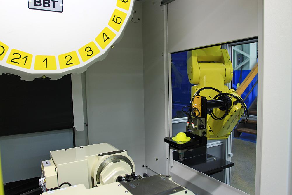
Automation can be simple, like this small robot loading a single machine, or large, complex systems involving multiple pieces of equipment.
Here are just a few of the questions you should think about when considering an automation cell:
The cell could be designed to handle a family of parts, which would minimize changeover, or it could be designed to handle almost anything within a certain size range. It’s important to note that flexible systems tend to cost more money.
Automation can be configured to allow some components to be automatically changed, but, as expected, this is more expensive than manually changing over components.
A lot of capacity is great, but, too much capacity can take up a lot of space and be a waste.
You might want to run the cell with the robot all the time, or you might want to use the machine manually without the robot for periods of time.
The Robot
The robot itself tends to be the main component in the automation cell and is the device that provides most of the required motions. For this discussion they are broken down into Cartesian and articulating-style robots.
The Cartesian, or X/Y, style of robot is basically grippers on two rails. These types of robots are often seen on turning centers. One rail brings the robot over the machine and one rail brings the robot down into the machine to the spindle.
Occasionally a third axis is used to give the robot better access to the spindle when overhead obstacles, such as the door configuration, limit direct access to the spindle. Quite often these types of robots are developed and sold as a semistandard option by the machine tool company and are purchased as part of a package along with the machine tool.
To ensure that your robot is suitable for the work environment, check its Ingress Protection (IP) rating.
Cartesian robots tend to be less costly than the articulating-arm robots, but they are not as flexible. They can only move back/forth and up/down along the rails. If all you are doing is load/unload and don’t expect your needs to expand beyond this, then a Cartesian robot may be a good option to consider.
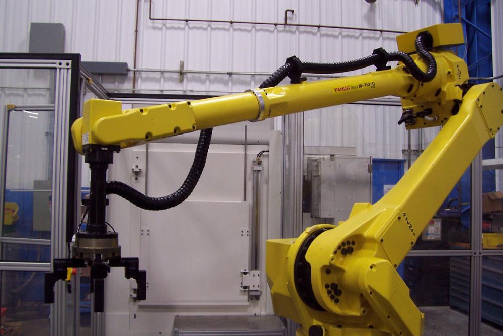
Articulating robots are the 6-axis arms that traditionally are thought of as industrial robots. They are very flexible and can articulate into some hard-to-reach places and perform many other tasks in addition to the basic loading/unloading.
These robots can be mounted on the floor, on a wall, and even upside down, depending on the requirements of the cell. This type of robot is produced in many different configurations by numerous companies for use in a range of industries.
It is important to make sure you purchase a robot that is designed for the intended application. For instance, one popular use of industrial robots is for laboratories. Robots designed for this clean application would not be suitable for the coolant-dripping and chip-covered environments that are prevalent in most machine tools.
To determine if your robot is suitable for the environment, check its Ingress Protection (IP) rating. This rating is a two-digit number, with the first digit being the solid particle protection and the second digit being the liquid protection. For example, a rating of IP63 means the robot is dust-tight and will handle dripping water, whereas a rating of IP66 means it is dust-tight and can handle water/liquids sprayed directly at it.
Industrial robots are sized by reach and payload. Maximum robot payload normally is stated from a specific point on the center of the faceplate on the robot. Everything that gets attached to the end of the robot needs to be included as part of the payload.
Many manufacturers are surprised to discover that payload includes not only the components to be loaded and unloaded, but also the grippers or other part-picking devices mounted to the end of the robot’s arm.
Additionally, the distance that the grippers are mounted from the face of the robot can affect the payload. Most robot manufacturers have payload calculators that allow you to evaluate the details of the EOAT for compliance with the maximum robot payload. While there is no substitute for using a formal payload calculator program, a good rule of thumb when using basic EOAT is half of the robot payload for the parts and half for the grippers/mounting plates.
The reach of the robot is another important consideration. The robot will need to reach not only the machine, but also the infeed/outfeed system.
End-of-Arm Tooling
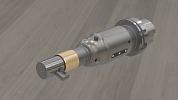
EOAT is the generic term for the tooling secured to the robot arm that performs the tasks the robot needs to do. For machine tool load/unload, this is normally pneumatic grippers that are used to grab the parts.
While methods such as suction cups or magnetics are sometimes used, the vast majority of machine tool load/unload EOATs are pneumatic grippers. Similar to the robot, make sure you choose good industrial-grade grippers designed for the environment they will be used in.
The initial question usually is how many grippers are needed for your EOAT.
When loading a single workholding position, such as one chuck on a lathe or one vise on a mill, the normal answer is two. One gripper grabs the finished machined part and removes it from the workholding, and one gripper already loaded with an incoming raw blank loads it into the now open workholding.
This concept of two grippers that enable the loading and unloading in one trip into the machine is popular for reducing the load/unload time, but it increases the weight on the end of the robot. For example, if you are loading two workholding positions, the first operation in one vise and second operation in the second vise, the number of grippers you need will increase even further. It is important to factor this in when calculating EOAT weight and, in turn, robot payload.
The next question to answer is what type of gripper is needed. Take one look at a gripper catalog and the choices will seem overwhelming; in reality, once you focus on the grippers designed for the machine tool loading/unloading task, the choices are usually much more manageable.
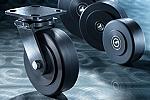
For grabbing square parts, rectangular parts, or parts with opposing flat surfaces, a two-jaw parallel close gripper typically is the gripper of choice.
For grabbing round or hex parts, three-jaw centric close grippers are preferred. Four-jaw grippers are suitable for picking parts out of a tray. Three-jaw grippers tend to have a jaw out of place when picking from a tray or when parts are presented in rows and columns. A four-jaw gripper will place a jaw in each corner, eliminating the interference.
Grippers also come in many different sizes and are rated by gripping force and stroke. Try to select the smallest gripper that will do the job to keep the robot EOAT weight down.
Most gripper suppliers offer finger blanks that can be machined or modified for better gripping of parts, similar to what is done with chuck or vise jaws. Unfortunately, these fingers cannot be machined in place like a vise or chuck jaw, so a simple fixture can be used to hold the fingers in proper place for machining.
When machining a set of fingers, machine them to allow the best possible opening for easier picking of incoming blanks. A chamfer or radius will also help facilitate better picking. Incoming parts are not always consistent. The extra opening and chamfers simply make it easier to accommodate the unplanned differences.
John Lucier is automation manager, Methods Machine Tools Inc., 978-639-9426, www.methodsmachine.com.


Keep up to date with the latest news, events, and technology for all things metal from our pair of monthly magazines written specifically for Canadian manufacturers!
Start Your Free Subscription
Easily access valuable industry resources now with full access to the digital edition of Canadian Metalworking.

Easily access valuable industry resources now with full access to the digital edition of Canadian Fabricating & Welding.