


Tooling Tips for High-speed Machining
Choose the right tool to combine speed and tight tolerances
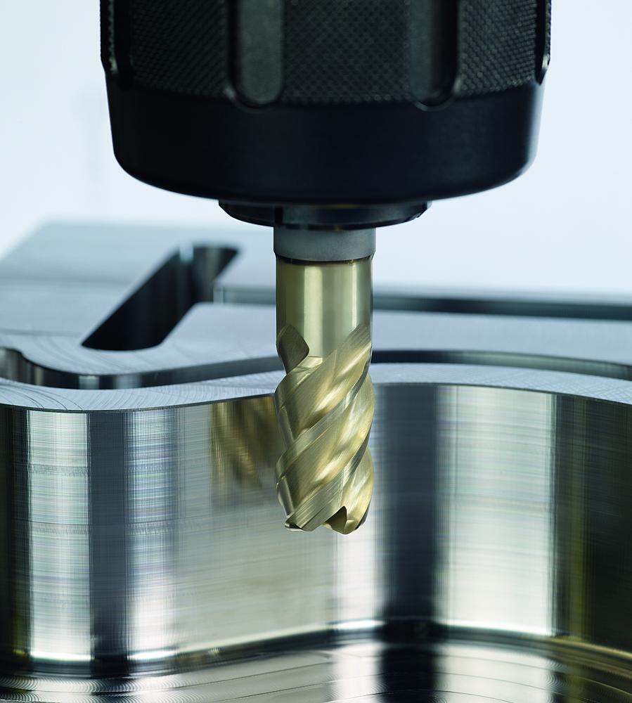
Successful high-speed milling requires a balance among every aspect of the cutting system, including the machine tool, software, chip removal, and cutting tool. Photo courtesy of Seco.
High-speed machining (HSM) shaves time off metal removal processes. Low speeds and feeds that remove a large amount of material are replaced with light depths of cuts made at high feed rates. Metal is removed quickly, and the resulting near-net-shape parts, with surface finishes often from 10 to 12 RMS, reduce the semi-finish and finish operations.
Successful use of HSM depends on how the machine is programmed, how the tooling is used, and the tooling itself. Tools need to be designed for the higher speeds.
As with most processes, the application determines the best tooling to use, but some rules of thumb should be considered for any HSM job.
Luke Pollock, product manager at Walter USA, described a high-speed mill tool: “A common HSM mill tool uses a triangle-shaped insert with rounded edges. It is positioned in the cutter with a high lead angle, which allows the tool to take advantage of the chip thinning principle. As the tool is advanced, you get a chip thickness that is smaller than the advancement of the tool. For example, a 0.003-in. chip thickness is produced rather than the 0.005 in. that tool was advanced. These two values would be equal for a tool with a 90-degree shoulder.
“Another method would be to engage a small percentage of the tool diameter so you get the chip thinning effect that allows you to elevate speed rates. The roughing inserts--and HSM is basically a roughing process--have to have a stronger edge and tougher coating than the finishing inserts.”
Use Dedicated Tools
Jay Ball, product manager--solid carbide end mills NAFTA, at Seco Tools LLC, said that it is important to have dedicated roughing and finishing tools. “Tight tolerances have become the industrial standard, and it is not uncommon for a customer to demand cutting tools with a 5-micron radius and diameter tolerance. Smaller tolerances are the wave of the future. To expect one tool to hold up during a roughing operation and use the same tool to finish and hold the tight tolerance is a stretch.”
Some tools combine roughing and finishing, but different cutting edges for each step help the tool to perform to close tolerances.
“Shoot for stability, and use a tool for the process it was designed for,” said Cullen Morrison, business development manager, threading and milling, at KOMET of America. “One thing to consider is optimizing the tool design. Inserts with a large nose radius are better suited for high feed rates and heavy stock removal but are prone to chatter in small depth of cut, light feed rate finishing applications. If you are taking a large depth of cut with a small nose radius, it is likely to change the way the forces act on the insert and you may get chatter.”
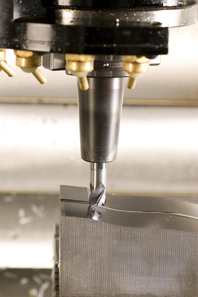
Tools for high-speed machining need to be rigid and as short as possible to avoid chatter or deflection. Photo courtesy of Walter USA.
Keep Tooling Short
High tool loads, especially in milling, bring out a system’s weakness. That weakness could be a poor rigid setup, a weak machine tool, or a loose bolt in fixturing that causes vibration. Machine tools are pushed to their limits for HSM, so the fixtures and tools have to be absolutely rigid to withstand the loads.
Depending on the manufacturer a tool may be designed with 1-1/2x, 2x, or 3x flute length diameter. The longer flute length is not as rigid as a short flute length so those tools may not work at the high speeds. Tools with shorter flute length need to be considered.
As with all applications, tool material and length-to-diameter ratio also affects HSM success. Morrison said that steel body tools are good to 3x or 4x diameter depending on the load. Carbide tools are better for HSM applications requiring a longer reach. Dampened steel tools can cut even further because they absorb vibrations happening at the cutting end.
“Tool manufacturers are adding tapered necks to some of the carbide tools, especially for the mould and die industry, so you have a stronger tool for a longer reach and the shanks of the tool will not rub the side walls of the mould cavity,” said Ball. “Those tapers increase strength by 10 to 20 per cent and give you the clearance to use a shorter, stubbier tool.”
Hold on to Balance
Tool balance is important when running at high RPMs. Most common tool designs with tool holders will work without a noticeable problem at speeds less than 7,000 to 8,000 RPM. But, over that speed, Morrison said you can start to see runout problems and decreased tool life.
“At higher speeds tool balance is exponentially more important as inertia begins to affect the tool, causing a compound problem of runout and imbalance that can even damage the machine spindle,” Morrison said. “Toolholder design also needs to be considered. Not all clamping systems will maintain their gripping force at a high rotational speed.”
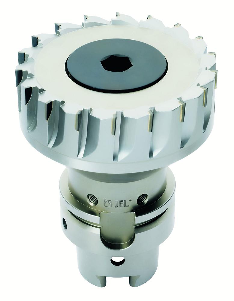
An integral shank design with brazed blades achieves a good tool balance for high RPMs. Photo courtesy of KOMET.
Ball said, “When you are high-speed machining you are taking a light radial and axial depth of cut, so you don’t have a tremendous amount of cutting pressure but you have to make sure your holds are rigid and balanced. You don’t see a lot of one-flute tools used in HSM because they are physically unbalanced by nature.
“Holders are critical for maintaining long, consistent tool life. It’s common for shrink fit holders to be used to hold the tight tolerances, but I also see the industry moving toward high-precision milling and collet chucks, as well as hydraulic chucks.”
Use Appropriate Coatings
Tool coatings play an important part in the HSM formula.
“The appropriate coatings will depend on the material being cut and the geometry of the insert,” said Pollock. “The geometry of the insert may require that the coating be very thin. And the thinner coating is typically better at heat resistance. A thicker coating will undergo more thermal expansion and doesn’t behave as well when heated—it can’t expand and contract as completely as a thin coat.”
The heat zone of a coating needs to be matched to what the tool is doing. Too much or not enough heat generation can cause a problem. Morrison said, “If the coating has a very low coefficient of friction, operations such as tapping may not generate enough heat to get the chip to break efficiently. The low heat level can create the tinfoil effect where the chip cannot break. Eventually chips build up in the hole and break the tap. If the coating cannot handle the heat generated by the operation, such as a high-feed mill, then it will break down quickly and expose the tool substrate, which will yield poor tool life.”
Keep the Process Clean
HSM generates a lot of chips very quickly. Ensuring their removal is critical whether you are dry machining and using an air blast, an air/oil mist, or using coolant.
Pollock said, “Sometimes air is adequate, but if it isn’t we prefer to use coolant just for getting the chips out of the way.”
“In hard milling you want to use an air/oil mist or air blast,” said Ball. “Coolant can thermal shock the cutting edge and prematurely wear out the tool. However, there are some cases where a manufacturer has to use coolant because it causes less wear than cutting hard chips. It’s a balancing act.
“If coolant is needed, there are several application-specific delivery options such as axial coolant lines and coolant channels that come out at the cutting edge.”
Morrison said, “A through-coolant system that is constant and consistent can maintain the heat absorbed by the insert at a fairly stable range to avoid thermal shock. Always use a clean, quality coolant and consider its oil concentration percentage.”
Chip load is also an area for attention, said Ball. “Not maintaining a constant chip load is one of the biggest issues I see in HSM. Consider whether the part you are machining and the tool you are using actually allow you to get to the feed rates you are programming. A widely varying chip load, or one that is too low or too high, will quickly wear out the tools.”
Sue Roberts can be reached at sroberts@canadianmetalworking.com.
KOMET of America Inc., 847-923-8400, www.komet.com
Seco North America, 248-528-5200, www.secotools.com
Walter USA LLC, 262-347-2545, www.walter-tools.com


subscribe now


Keep up to date with the latest news, events, and technology for all things metal from our pair of monthly magazines written specifically for Canadian manufacturers!
Start Your Free Subscription- Stay connected from anywhere

Easily access valuable industry resources now with full access to the digital edition of Canadian Metalworking.

Easily access valuable industry resources now with full access to the digital edition of Canadian Fabricating & Welding.