


The Importance of Proper Programming Techniques
Using up-to-date CAD/CAM software wisely can reduce programming and production time, improve safety and quality
The correct CAM software depends on a number of factors, but the most important are machine type and part configuration.
Moldmakers are especially sophisticated when it comes to keeping up with new technology and trends in the marketplace. To keep up with their requirements, CAM software developers need to supply various CAM products for applications from complex three- and five-axis machining to programming of mills, lathes, and wire EDMs.
No single CAM package fits the needs of all companies. The right program depends on a number of factors, the most important being the type of machine being used and the product being produced on that machine.
Safe Programming
Reducing programming time has always been important to the overall production time for a part, but the need for safe machining has become more critical as a growing number of mold companies are introducing lights-out, or unmanned, operation for overnight or weekend shifts.
The key to safe machining is accuracy. To achieve the best accuracy possible, you should use solid stock models that represent each machining stage. You also should optimize/clip toolpaths relative to those models.
Different aspects of this functionality are available in today’s software packages, such as Delcam’s PowerMILL and FeatureCAM. After each machining stage has been completed, models give a precise representation of the material still remaining on the part. These models help to ensure that the cutter is never asked to remove more material than it can safely cut. At the same time, the stock models ensure that toolpaths are not produced where no material remains so the machine tool is never left cutting air.
A number of CAM programs incorporate strategies based on the extent of cutter engagement to produce more consistent loading on the tool, which allows the highest feed rate to be used. However, these options usually are limited to the initial roughing operation, or to only roughing and rest-roughing.
Stock engagement technology also should be employed with all of the system’s finishing and rest-finishing strategies, ensuring that the safest possible toolpaths are run on the machine at all stages. Stock model technology is now available for turn/mill toolpaths.
In addition to safe machining, time savings are crucial. Many toolpath editing options make it easier to produce multiple copies of any duplicated item. For example, for machining a series of cavities into a mold tool, the programmer can specify an array of multiple copies in one operation, using approaches such as a number of rows and columns or a radial spacing around a central point. Once the copies have been produced, the complete series of toolpaths can be resequenced to minimize tool changes.
Existing software has incorporated sketching functions for several years, for example, to draw boundaries within the model to limit individual machining strategies to particular areas of the part. This now has been enhanced with a number of new editing options, including the ability to offset or transform curves, to flatten 3-D curves into 2-D curves, and to project 2-D curves onto 3-D surfaces.
Today’s software runs faster than previous versions thanks to the addition of 64-bit processing and the latest multithreading technologies that allow more efficient toolpath generation, especially for shops machining large or complex parts. In addition, improved memory management within the software further reduces calculation times.
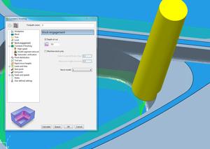
Stock engagement technology should be used during finishing and rest-finishing to ensure the safest possible toolpaths.
Data exchange is important in reducing programming time. Delcam’s Exchange software, for instance, can be used as an additional import mechanism so that all the formats supported by Exchange can be imported into the CAM software. These include direct translations from systems such as CATIA® V5, Siemens NX® and Solid Edge®, Pro/ENGINEER®, AutoCAD® Inventor, SolidWorks®, and RhinoCAM®, as well as support for standard formats like Parasolid®, ACIS®, IGES®, and STEP. Some software also includes automatic tools to repair problems caused by data exchange, such as missing or duplicated surfaces and gaps or overlaps between surfaces.
A Look at FeatureCAM 2011
An enhancement for 2-D work in the release of FeatureCAM 2011 is the ability to machine parts that are larger than the travels of the machine tool.
If the machine has a table that can index around the Z axis, this software can divide the component into pieces and generate the required series of machining operations. Finish-machining of flat areas has been made more efficient with improved detection of these surfaces. The CAM software then automatically adds the appropriate extra Z-level into the toolpath to give accurate finishing.
This option will be most beneficial for machining a series of pockets with flat bottoms at different heights, Delcam states.
The milling capabilities of this version also have been enhanced through the incorporation of strategies from Delcam’s PowerMILL system for high-speed and five-axis machining. The addition of Race Line Machining strategy allows the roughing passes to be smoothed out progressively as the toolpaths move farther from the main form.
For five-axis machining, more options have been added to the collision avoidance functionality. These give the user more control over the movements chosen by the software to avoid potential problems and so help to reduce sudden changes in direction.
Five-axis drilling has been improved in this version of the software, with new options to program and edit five-axis hole creation, even when the items are supplied as simple circles in space rather than fully defined solids.
subscribe now


Keep up to date with the latest news, events, and technology for all things metal from our pair of monthly magazines written specifically for Canadian manufacturers!
Start Your Free Subscription- Stay connected from anywhere

Easily access valuable industry resources now with full access to the digital edition of Canadian Metalworking.

Easily access valuable industry resources now with full access to the digital edition of Canadian Fabricating & Welding.
- Trending Articles