Editor
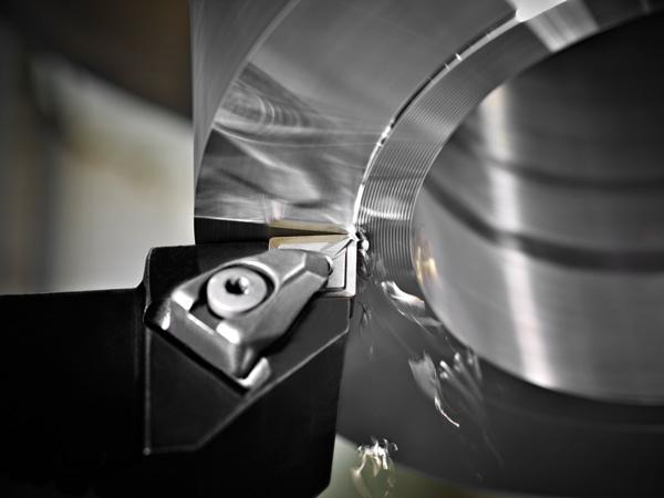
The two most important details to watch for during a turning operation are chip color and chip size. Photo courtesy of Seco Tools.
In a turning operation, you can learn a lot from the chips being produced.
Chip appearance will vary based on several factors, but workpiece material is the main driver. The two most important details to watch for are chip color and chip size. The sizes of chips produced when cutting cast iron are vastly different from those made when cutting steel. And, depending on the material you are machining, there are certain colors to look for as chips are created.
“If you are machining carbon-alloy steels, you don’t want to see dull gray chips; you want to see chips that are blue,” explained Steve Geisel, senior product manager for Iscar Canada. “When chips appear blue, it tells you that the heat generated in the cut is being directed into the chip and not being kept in the insert or the workpiece material.”
Heat absorbed into the insert will reduce tool life and create poor surface finishes. It also might harden the workpiece, reducing tool life even further.
“Just by looking at the chip’s size and color, you should be able to tell how the cutting tool is running,” Geisel said. “These two factors will tell you if you are using the proper chip former for the DOC, spindle speed, and feed rate. It just gives you so much feedback.”
Of the six main workpiece material groups, steels (ISO P), stainless steels (ISO M), heat-resistant superalloys (ISO S), and nonferrous materials (ISO N) often produce chips that are not ideal.
In low-carbon steel, for example, the low carbon content makes it harder for chips to harden and break away. There is not enough martensite formation, which means that the material will stay soft and sticky.
Creating a perfect chip isn’t easy, but it can be aided by using an insert with a chip breaker.
Chip breakers are part of the macrogeometry of the insert. The size, geometry, and location of the chip breaker vary by material and depth of cut (DOC).
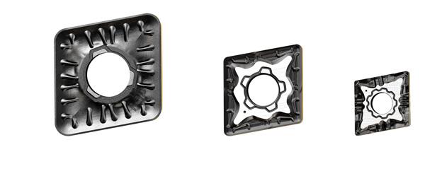
It’s important to use the correct insert and chip former based on DOC, feed rate, spindle speed, and surface finish. Photo courtesy of Iscar Canada.
“Chip breakers, or what I like to call chip formers, are designed to form the chip in such a way that it breaks into a manageable size,” said Geisel. “No matter what type of material you are cutting, the last thing you want to produce are long, stringy chips. There is no excuse for creating them.”
According to Geisel, long, stringy chips are an indication that either the cutting parameters are incorrect for the insert being used or an incorrect chip breaker is being used for the cutting parameters being run.
Chips normally break off in one of three ways: they self-break, they break against the tool, or they break against the workpiece. Chips that are an ideal size pose no threat to the machine and will not damage the part, toolholder, or insert.
It’s when chips break poorly that birdnesting occurs. When the system produces long, stringy chips, commonly referred to as birdnests, the operator must manually clear them from the machining envelope, creating a health and safety issue for the operator, and also pause the machine, increasing the cycle time.
“When chips form in these birdnests, they get wrapped up around the chuck and cause damage, but what we see shops most concerned about is the safety issue,” said Chad Miller, product manager – turning and advance materials for Seco Tools.
Bad chip breaking also affects productivity. Long chips take up more room in the hopper, which requires it to be emptied more often, but it’s not as full in terms of weight of chips. When combined with the time lost due to stopping the machine and removing chips, productivity is reduced and per-part costs are higher.
“In materials that create long chips, having the correct chip groove can make a big difference,” said Miller.
Seco’s FF2 is a finishing chip breaker designed for smaller DOCs and relatively low feeds (f = 0.008 to 0.025 inch, ap = 0.020 to 0.157 in.). Its design features a dimple and a very large rake angle at the nose. It also has a short, positive protection chamfer and is “narrow” in the front.
Slots are pressed into the carbide help to deliver coolant directly to the tip of the tool to help break the chip.
“All of these things together -- the geometries, coolant, grade, and coating -- enable the chip to break easily and move out of the cutting zone,” said Miller.
According to Iscar’s Geisel, it is critical to understand what type of operation you are performing.
“In turning we say that there are four types of operations: finishing, medium, roughing, and heavy roughing,” he said. “We design chip formers for all four categories, and it’s important to use the correct chip former based on your DOC; the feed rate you want to run at; the spindle speed; and, when finishing, the type of surface finish you are trying to achieve.”
The chip breaker’s design is based on the DOC and also feed rate. For example, a roughing insert’s chip breaker must be designed is such a way that it can handle the high cutting force of the operation.
The type of turning operation also affects chip formation.
According to Miller, ID and OD turning with small DOCs, profile, and face turning requires a tight, sharp chip breaker (positive protection chamfer, relatively big rake angle, and a narrow nose design). A grooving operation has different requirements. Durring this process it’s preferable to produce small “comma” or “clock spring” chips that evacuate from the groove without scratching the side surfaces of the groove. You need to make chips that are smaller than the groove. You also need to get the right radius for the chip – how it curls – depending on the feed rate limits you set. The depth of the chip breaker’s pit affects both chip width and chip radius.
The last way to aid chip breaking is with coolant use – specifically, high-pressure coolant (HPC).
During the application of HPC, a jet of coolant creates a “hydraulic wedge” between the chip and the insert. Not only does this cool the zone better, it forces the chip away from the insert face quickly, and it breaks the chip into smaller pieces.
“This wedge action occurs because the coolant is directed at a very specific area,” explained Kevin Burton, turning product manager for Sandvik Coromant Canada. “For cutting materials that produce long chips, properly directed high-pressure coolant can have a dramatic effect on chip control and evacuation.”
In a typical flood-coolant setup, coolant is sprayed from a location that typically is far away from the cutting edge. This causes the chip to act as an umbrella, deflecting the coolant away from the cutting zone. When this happens, the cut is not well-lubricated or cooled at the cutting edge.
“We like to think of this as high-precision coolant application,” said Burton. “When employing flood-style coolant, all you do is cool the chip. While cooling the chip can help it break, precision coolant application can cool it, break it, and move it out of the cutting area.”


Keep up to date with the latest news, events, and technology for all things metal from our pair of monthly magazines written specifically for Canadian manufacturers!
Start Your Free Subscription
Easily access valuable industry resources now with full access to the digital edition of Canadian Metalworking.

Easily access valuable industry resources now with full access to the digital edition of Canadian Fabricating & Welding.