Editor
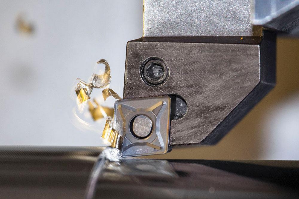
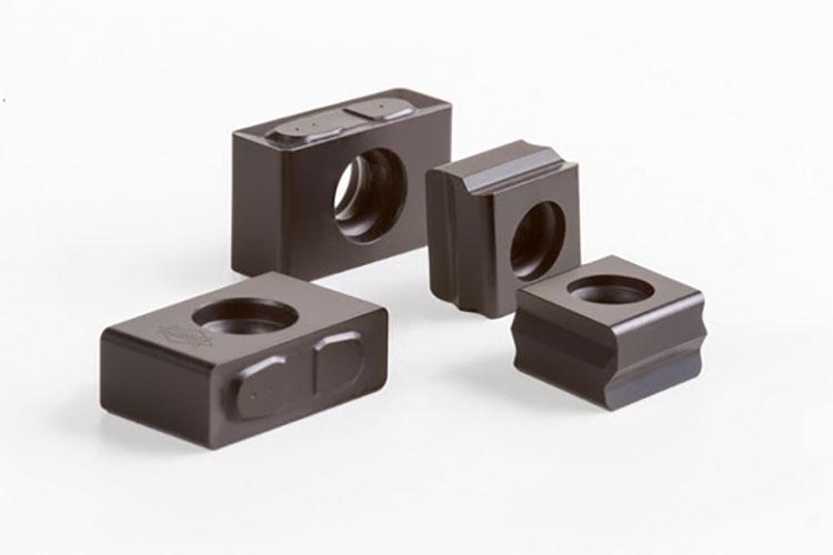
Breaking the chip into the traditional 6s and 9s shape allows the coolant to get down to where the heat is being generated at the cutting edge and prolongs tool life. Photo courtesy of Dormer Pramet.
In the machining world, you live and die with your chips. If you’re making chips, you’re making money.
Many factors influence a machinist’s ability to create workpieces that are both on time and on spec. The machine, material, software, workholding, toolholding, coolant, tooling, and labour must all come together to make a correct, shippable part. Oftentimes, the smallest detail can have the biggest impact.
The literal smallest detail in this equation typically is the tool—a small insert made of coated or uncoated carbide that removes material from the programmed toolpath at a set depth of cut and speed. Tools are the lifeblood of a shop. Without tools, a shop stops.
Inserts wear. That’s part of the process. But they should wear evenly, almost predictably. When that doesn’t happen, productivity falls, and when it happens suddenly and unexpectedly, it can damage the workpiece and even parts of the machine.
Generally speaking, proper insert wear should occur on the flank of the insert and should not exceed 0.005 to 0.015 inch, depending on insert size.
Heat, speeds and feeds, chip load, approach angle, and many other factors influence wear type, location, and speed. Each of these factors can lead to a different type of wear. Instability in the setup leads to chipping; excessive heat can cause crater wear and excessively quick flank wear; and problems with incorrect cutting data can affect wear in many ways, up to and including catastrophic failure.
It is always best practice to choose the insert and starting parameters that best suits your machining operation.
For example in a threading operation, even wear should occur across the leading flank and nose radius. Uneven wear will reduce tool life and produce poor surface finish.
According to Scott Golden, vice president of sales and marketing for Vargus USA, programming 60-degree threads with a modified flank infeed will create better chip flow and to prevent re-cutting the chip.
He also recommends the easiest way to reduce wear: use the fewest cutting passes when creating your thread.
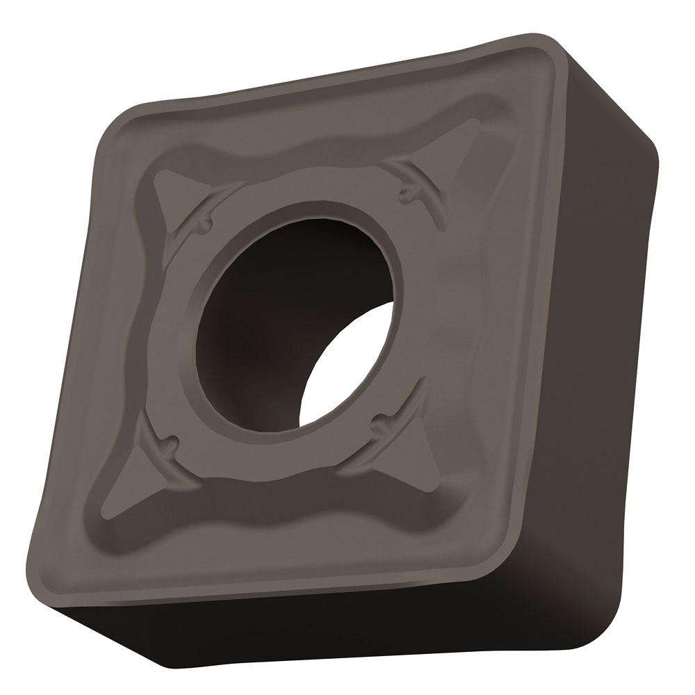
Hundreds of grade, coating, and geometry combinations exist to tackle every machining operation. Photo courtesy of Dormer Pramet.
“The longer the insert is in the cut, the more wear there is on the insert, shortening tool life,” said Golden.
It’s not always that simple, however. Eight types of tool wear exist, and they have many causes and solutions.
“Flank wear occurs on the corner of the insert, because this edge deteriorates during the cutting process,” said Dan Cormier, Dormer Pramet application specialist for Canada.
This wear can be seen on the side (flank) of the insert and there are several ways to identify it. For instance, the surface finish will get worse as flank wear increases.
“You can visually see the flank wear on some inserts, and you can also feel a deterioration of the insert edge by running your nail or finger along the cutting edge,” said Cormier.
The heat generated during cutting causes the flank of the insert to wear down. This type of wear also is measurable and, therefore, predictable, enabling you to change your inserts at the appropriate time.
Because flank wear occurs naturally during cutting, eliminating it is impossible.
“Inserts will wear in the cut,” said Cormier. “At times flank wear can be reduced by switching to a harder insert, but that could introduce other types of wear such as chipping, which is not predictable.”
Flank wear that is too rapid, however, has specific causes that can be remedied.
“Uniform flank wear is the optimum type of wear, but it often is combined with some chipping of the cutting edge towards the end of tool life,” said Mapal Optimization Department Specialist Wilhelm Ehard.
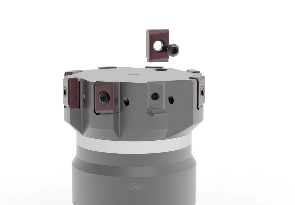
Eight types of tool wear exist that will break down inserts as they cut, and they have many causes and solutions. Photo courtesy of Dormer Pramet.
If you are experiencing flank wear that is happening too quickly, reducing cutting speed, increasing the feed rate, and picking a more wear-resistant grade can help.
Cratering, or crater wear, is a concave wear pattern on the rake face of the insert a short distance from the cutting edge.
It is caused by a chemical reaction between the workpiece material and the insert, and it happens as chips flow over the insert’s face at very high temperature. It develops as severe friction between the chip and rake face wears the insert.
“This type of wear is commonly observed where a continuous chip is formed, usually in ductile materials,” said Mapal’s Dario Trevino, also a member of the optimization department. “If unchecked, this erosion can continue until a breakthrough occurs at the cutting edge.”
The elimination of cratering is not always possible, but good results often can be obtained if crater growth is limited so that the maximum allowable flank wear is reached before crater breakthrough occurs.
Crater wear also occurs when the insert is too soft for the heat generated in the cut. Increasing the hardness of the insert will reduce or eliminate cratering. Reducing cutting speed and then the feed will help reduce this type of wear.
Built-up edge (BUE) occurs when the material you are cutting adheres to, and builds up on, the surface of the insert.
“This is very prevalent in the machining of aluminum and stainless steel,” said Cormier. “Because like materials marry to like materials, BUE only gets worse after it begins. Eventually, it gets so thick that proper cutting action is lost and the insert breaks.”
The common fix for BUE is to raise your surface footage to add more heat into the cut and lessen the adherence. Increasing your coolant percentage also can add more lubricity to the cut and reduce BUE, according to Cormier.
Chipping happens to an insert when it is heavily shocked. It tends to occur during interrupted cutting or in cutting with long overhangs, which leads to vibrations.
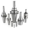
Inserts are designed with different hardnesses to handle the varying conditions encountered during machining. Photo courtesy of Mapal.
“This type of edge failure is the most unpredictable, and steps should be taken to reduce vibration,” said Cormier.
There are a few ways to reduce chipping of an insert. Start by selecting a tougher grade or an insert with a stronger cutting edge. Reducing feed (especially at the beginning of the cut), increasing cutting speed, and improving overall stability of the process should all help reduce chipping of the cutting edge.
According to Cormier, notching of an insert occurs when the surface hardness of the material is much harder than the base material. It is common when machining stainless steels and nickel-based alloys, in which the surface hardness of the workpiece can be up to 30 Rockwell Hardness C harder than the material underneath.
“Increasing your edge prep and varying your depths of cut can reduce notching,” said Cormier.
Plastic deformation of the cutting edge of inserts happens because of the combination of high temperature and high cutting forces, said Ehard. It occurs when the carbide at the cutting edge is softened by the high temperatures produced during machining operations.
“It is most common when operating conditions are severe enough to generate intense heat and is normally associated with the machining of hardened materials,” added Trevino.
When plastic deformation occurs, a large section of the cutting edge becomes very hot, and the heavy cutting pressure compresses the nose of the cutting edge, which lowers the face in the nose area. This wear reduces the relief under the nose, increases the width of the wear land in that area, and leads to poor chip control, poor surface finish, increased cutting forces, and shorter tool life.
The proper application of cutting fluid, a cutting tool material with higher wear resistance, additional coatings, and reducing cutting data can minimize this deformation.
Because this type of wear is caused by a combination of heat and force, reducing one or both can remedy it.
“Plastic deformation is a result of excessive heat in the cutting zone. Ideally, the heat should be transferred to the chip and out of the workpiece. This is best achieved by modifying the cutting speed and feed rate, or with chipbreakers,” said Golden. “Fortunately, plastic deformation is not as common today as a failure mode because of advances in carbide-alloying elements and coatings.”
Thermal cracking appears as cracks that are perpendicular to the cutting edge, caused by large, rapid temperature changes at the cutting edge, said Ehard. They often occur in interrupted cutting or during the machining of hardened workpieces on which cutting fluid is applied intermittently.
“Generally, in these cases the workpiece will end up with poor quality. This could mean a poor surface finish, wrong size, and wrong part geometry,” he said.
To combat thermal cracking, use a tougher, more wear-resistant grade. However, the problem is likely an incorrect cutting fluid strategy. Applying high-volume, high-pressure coolant—or in situations that will allow, using no coolant—will also help.
The worst-case scenario for any machining operation, in terms of tool wear, is complete failure (breakage) of the tool. While rare when each part of the machining process is chosen correctly, tools can still break if one part of the process fails.
“Insert failures occur when the wrong grade and chipbreaker combination is chosen for the cutting conditions,” said Cormier. “Each manufacturer publishes proper parameters for each insert, and choosing an insert for your application specifics will help eliminate failure.”
Hundreds of grade, coating, and geometry combinations exist to tackle every machining operation
Keeping any type of tool wear to a minimum first requires selecting the proper insert for the machining job at hand.
Inserts are designed with different hardnesses to handle the varying conditions encountered during machining. For example, inserts with a higher cobalt content are inherently tougher and, therefore, perfect for milling or turning through interruptions. Inserts with lower cobalt contents are harder, so they are well-suited for finishing operations and the high heat encountered in machining of superalloys.
In terms of wear, coatings also play an important role.
“Coatings have a great impact on insert wear because they increase the surface hardness of the insert, allowing it to withstand higher heats without edge deterioration,” explained Dan Cormier, Dormer Pramet application specialist for Canada. “By polishing the coating after deposition, the insert surface is less prone to building up, and chip formation is improved.”
The geometry of the insert also is important.
Whether in negative or positive geometries, a lot of development has gone into creating chipbreakers that create the optimal chip. Breaking the chip into the traditional 6s and 9s shape allows the coolant to get down to where the heat is being generated at the cutting edge and prolongs tool life. Long, stringy chips add a lot of heat to the cutting edge, which speeds up edge wear. They also are very difficult to get out of the work zone and can lead to bird-nesting.
An insert’s edge prep is determined by the type of operation.
“Edge preps protect the corners of the inserts from the different shocks that occur during machining,” added Cormier. “Preps work the best when they correspond to the type of cutting being done.”
For example, an insert with a heavy hone will not work well in a light finishing operation, but it will work well in heavy roughing applications.
Editor Joe Thompson can be reached at jthompson@canadianmetalworking.com.
Dormer Pramet, www.dormerpramet.com
Mapal, www.mapal.com
Vargus USA, www.vargususa.com


Keep up to date with the latest news, events, and technology for all things metal from our pair of monthly magazines written specifically for Canadian manufacturers!
Start Your Free Subscription
Easily access valuable industry resources now with full access to the digital edition of Canadian Metalworking.

Easily access valuable industry resources now with full access to the digital edition of Canadian Fabricating & Welding.