President
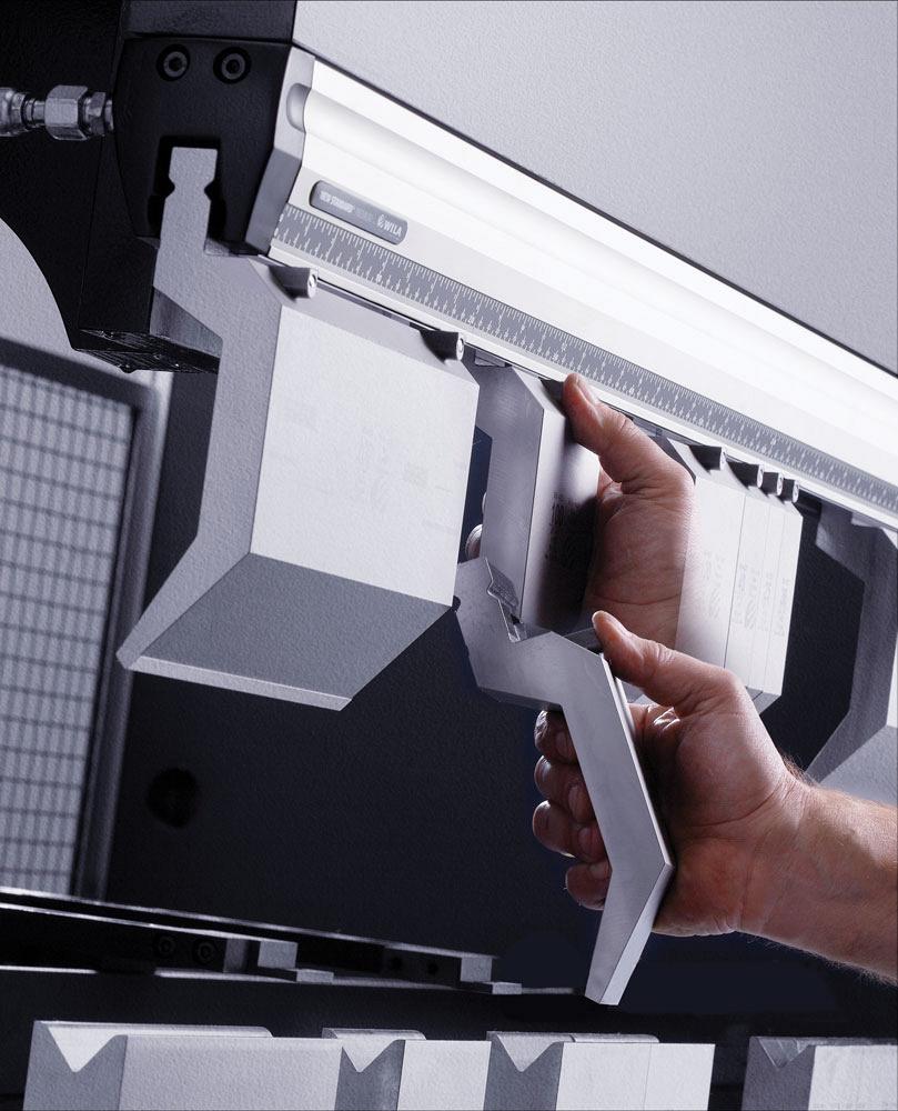
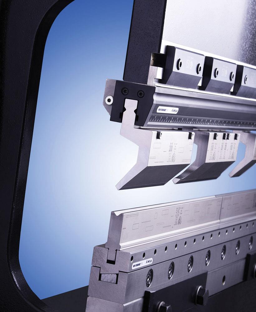
Hydraulic clamping in combination with tool self-seating and vertical loading significantly speeds up tooling setup time.
The traditional means of clamping tooling in a press brake is to use mechanical clamping plates and set screws. This can be a slow, inaccurate process that can detract from optimizing press brake productivity.
Over the last 30 years, more press brake manufacturers have begun offering hydraulic clamping of tools as standard or a recommended option, and more customers are upgrading their existing press brakes with hydraulic clamping systems that can be quickly and easily retrofitted to their machines.
As press brakes became more versatile and accurate, there was a natural demand that the tooling be faster to set up and be equally precise, without having to make continuous adjustments. The introduction of hydraulic clamping systems for both the ram and bed of the machine, along with precision segmented tooling, addressed this need for faster and more accurate tooling setup. Early hydraulic clamping systems often were bulky in design, limiting bending freedom, and did not automatically seat the tooling. However, the latest press brake tooling systems feature clamping that is intuitively designed and automatically clamps, seats, and aligns all the tooling in the press brake in seconds.
The majority of today’s new precision press brakes feature ram repeatability accuracy of ± 0.01 millimeters. To take advantage of this machine accuracy, clamping tool holders and the tooling should be of equal accuracy to be able to produce quality parts consistently. Top and bot-tom clamping systems also are available with adjustments in both the vertical and horizontal planes to adjust initially for tolerances in the press brake.
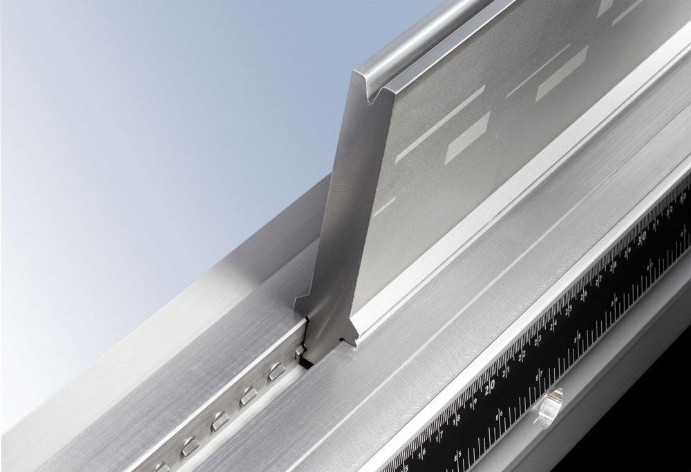
Alignment pins are used in the clamping system to adjust the tool holder front to back to be in perfect alignment to the backgauge, allowing the production of parts with correct flange lengths. An adjustable wedge is available in either the top or bottom clamping tool holder to compensate for machine tolerances and to bring the ram and bed parallel to each other, enabling consistent bend angles. Retrofitting precision-ground clamping tool holders can also significantly improve the accuracy of the parts being formed on older machines.
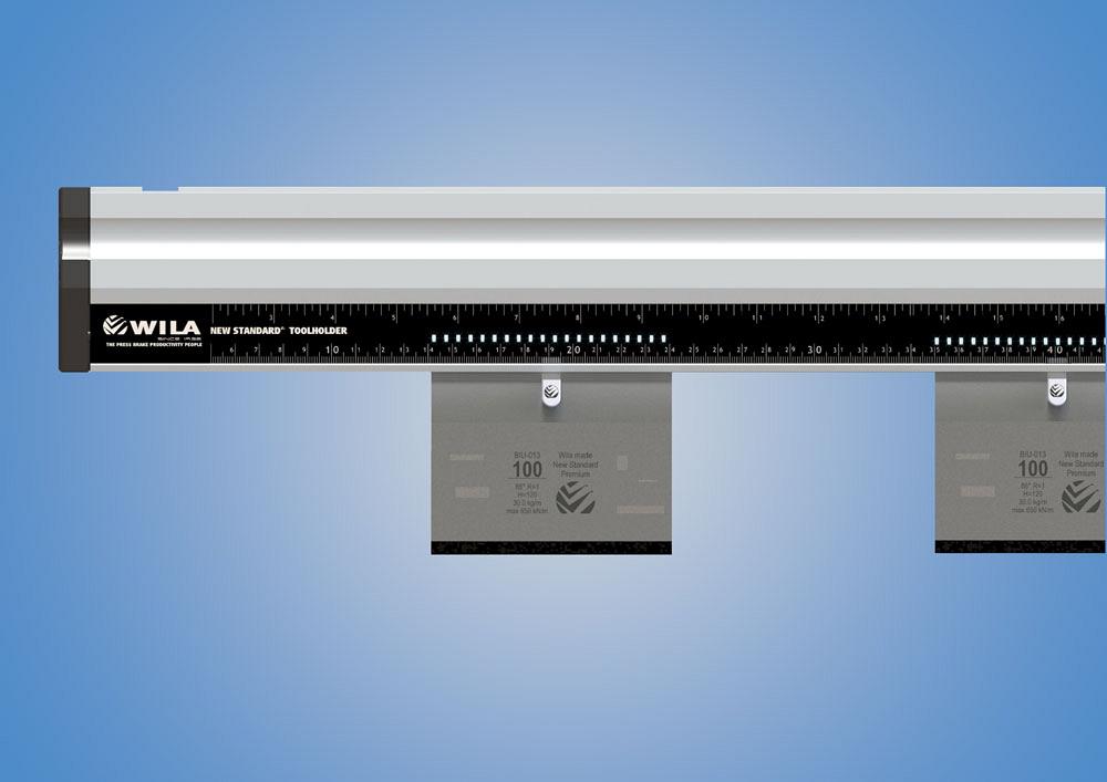
The use of hydraulic clamping pins that put individualized pressure on each V-die segment was an improvement over earlier designs that used hydraulic clamping bars incorporated into the bottom die holders. While the hydraulic clamping bars were fast to clamp and unclamp tools, multiple V-die segments located within a bar length did not always have the same clamp-ing force applied because of small tolerances in die tangs or because of the clamping bar tilting slightly at an angle, depending on where V-die segments were placed. A series of hydraulic clamping pins along the full length of the tool holder eliminates this problem and provides superior clamping force and die alignment.
The basic method of hydraulic clamping in both upper and lower clamping systems is to use a hydraulic bladder that exerts 35- to 45-bar pressure on individual clamping pins that are placed about 10 mm apart. Springs at each clamping pin release the pins quickly when hydraulic clamping is deactivated. A light-weight hydraulic oil helps ensure quick clamp and unclamp speed. A groove on the back of the V-die tang allows the clamping pins to lock the die segments in place, preventing the dies from being knocked out of position by the sheet part or from being pulled out of the die holder when making acute bends.
Today hydraulic clamping is available on practically any type and size press brake, both new machines and as a retrofit. On new press brakes the hydraulic operation of the clamping is normally interfaced with the machine hydraulics. A pressure-reduction valve helps reduce the press brake hydraulic pressure to be in the hydraulic pressure range needed for tool clamping. With a clamping retrofit to an existing press brake, a small independent hydraulic pump with remote control operates the hydraulic clamping.
Various hydraulic clamping systems are available, depending on the tooling style being used. Different models of clamping systems also are available, depending on the tonnage of the press brake and the load requirements of the planned bending applications. Hydraulic clamping systems are available with maximum load ranges from 180 tons per meter to 800 tons/m.
The upper and lower clamping systems also are available with different options for mounting to the ram and bed of the machine, so normally no modification to the press brake is required to incorporate hydraulic clamping. A hydraulic clamping retrofit typically takes four hours.
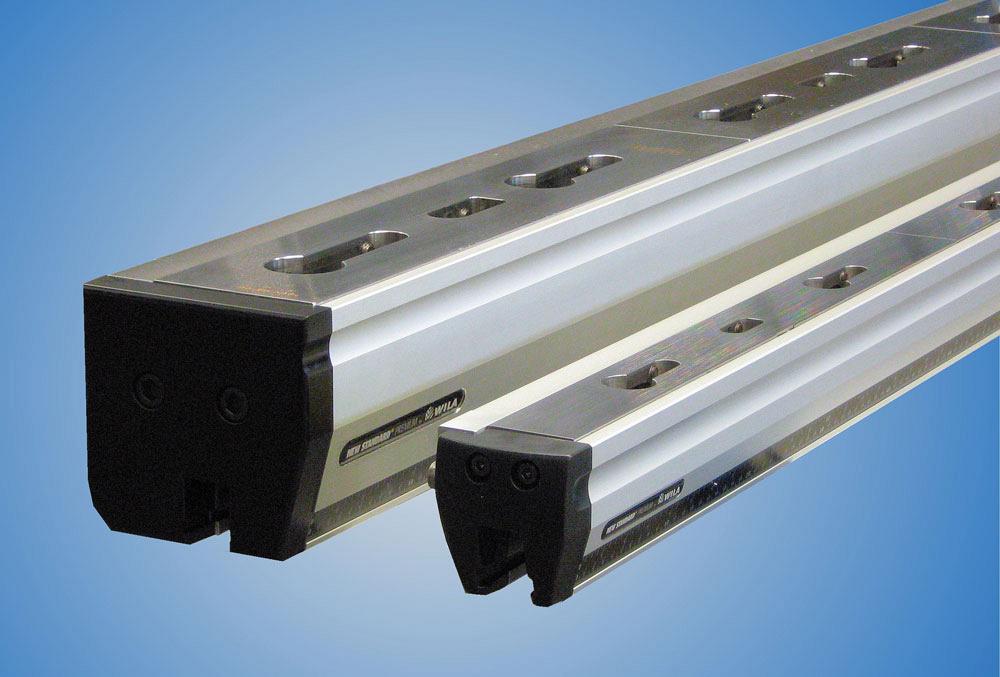
Different sizes and models of clamping systems are available depending on press brake tonnage and maximum load-rating needs.
With the increasing popularity of smaller electric press brakes, a pneumatically activated mechanically self-locking system has been developed that uses normal shop air, so no hydraulics are required. This style of clamping system features fast clamp/unclamp speed with tool clamping forces similar to those of hydraulic clamping systems. Pneumatic clamp-ing system are available for both top and bottom clamping of tools and suitable for electric and hybrid press brakes that don’t use hydraulics, as well as for automated bending cells that require quick clamping speed.
Another more recent development is to incorporate LEDs into the clamping systems. The LEDs help the operator place the tools in the correct position in the clamping system and then guide the operator through the bending sequence by lighting up where the next bend is to be made. This speeds up the bending process and helps reduce errors.
A further development, in alignment with Industry 4.0, is to incorporate intelligence in both the clamping systems and the press brake tooling. With this tooling concept, an ID tag is incorporated into each tool segment that gives all the critical technical information about the tool (tool height, profile, radius, angle, load rating.), and electronics built into the clamping systems identify and read all of the tooling data as well as the exact location of each tool at all times. This system is suitable for use in automated bending systems that use a robot for automatic tooling change.
Tool clamping systems have come a long way in speed, accuracy and overall capabilities to be a key driver in improving press brake productivity.
Gunter Glocker is a senior advisor at Wila USA and can be reached at gglocker@wilausa.com, www.wilausa.com.


Keep up to date with the latest news, events, and technology for all things metal from our pair of monthly magazines written specifically for Canadian manufacturers!
Start Your Free Subscription
Easily access valuable industry resources now with full access to the digital edition of Canadian Metalworking.

Easily access valuable industry resources now with full access to the digital edition of Canadian Fabricating & Welding.