Into the Fold
The story of metal folding in precision fabrication
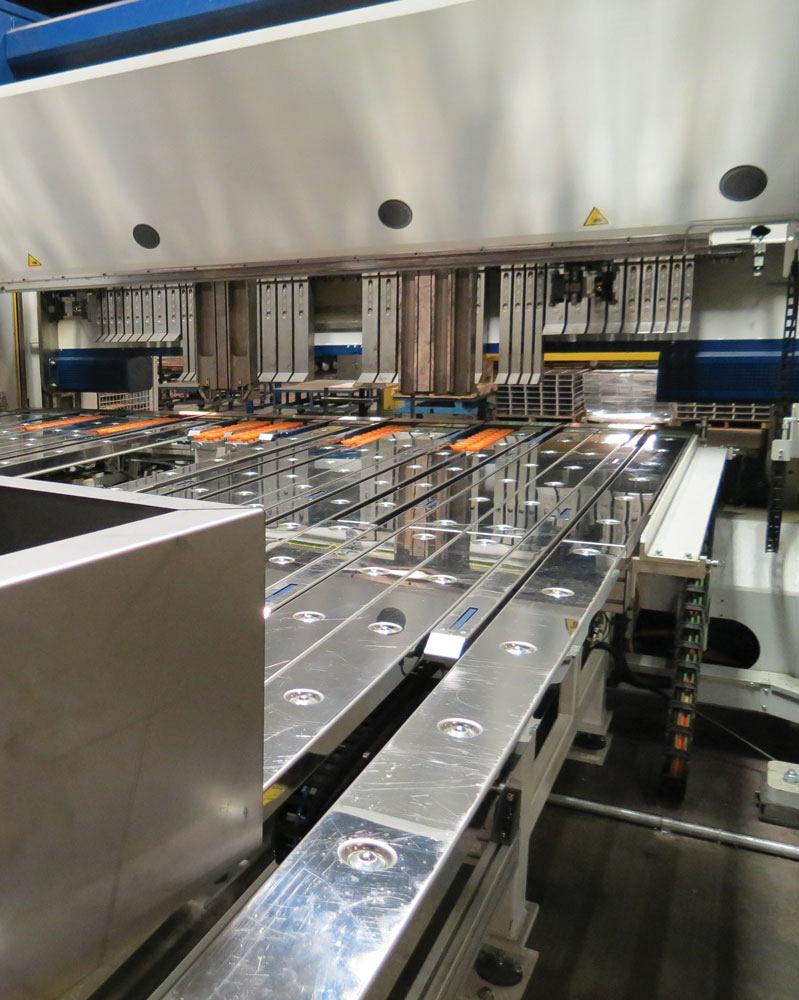
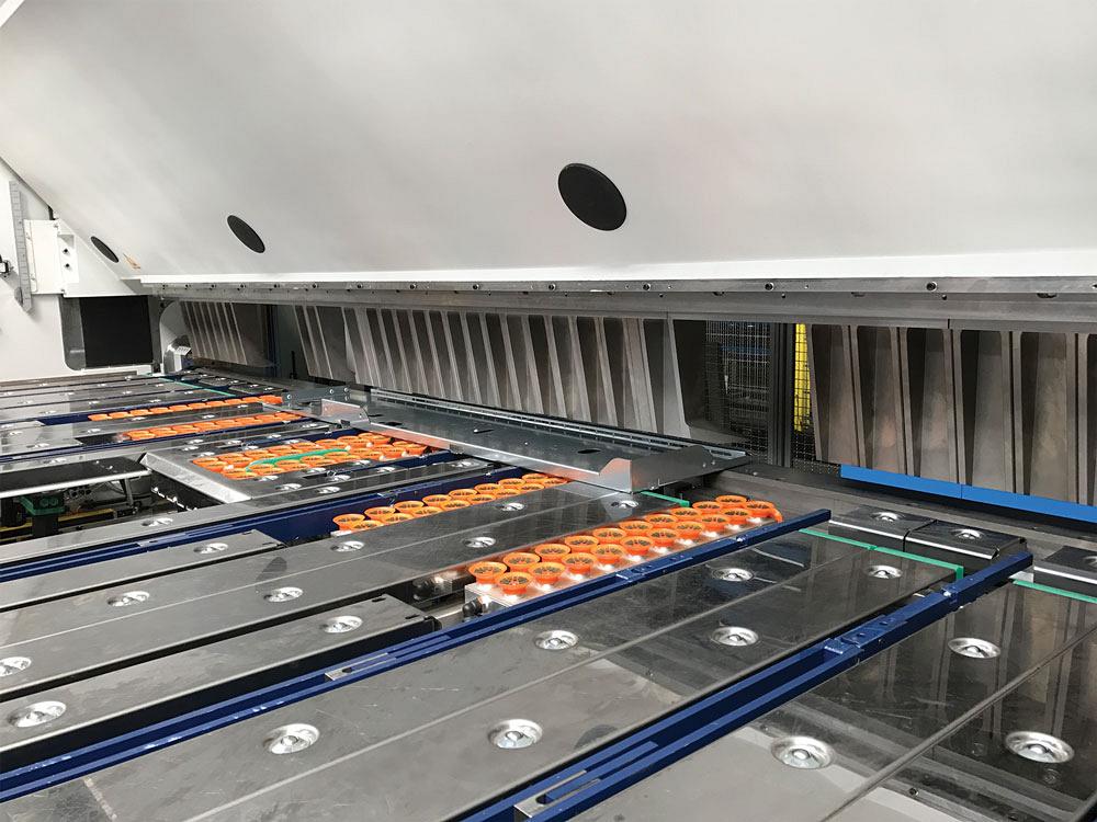
Clamping beam tools and suction backgauges (shown in orange) that maneuver the workpiece allow for the efficient folding of tall adjacent flanges. An operator runs this machine standing by a U-shaped backgauge table.
In the early 1990s a sheet metal bending machine started having an increased presence in the North American market. The technology wasn’t common this side of the Atlantic, though it had by that time been long established in Europe. It hit the roofing and architectural fabrication market first, then gradually made its way to the precision and industrial segments.
It didn’t look anything like a press brake, the dominant bending machine of metal fabrication. It also wasn’t a leaf (also called hand, or box and pan) brake, long a staple of roofing and architectural fabricators. But its operation did resemble that of a leaf brake, with a leaf (or beam) rotating upward to bend up (and at first, it was always up) a flange.
Germans called it “schwenkbiegemaschinen”, translated as “swing bending machine.” Fabricators here knew it as the folding machine or, more casually, the folder.
The Folder 101
Folding machines aren’t sold in tonnages that describe the maximum forming force they exert. They instead are sold in thickness capacity and lengths, usually up to 0.25-inch carbon steel (though some are even heavier-duty) across a bed length that could be 10 feet, 17.5 ft., or more. Of course, capacity varies by material type. Stainless capacity is typically 60 to 70 per cent of the mild steel capacity, and aluminum is about 130 per cent.
“We don’t talk in terms of tonnage, though machines have tonnage values when it comes to the clamping force,” said Bill Kennedy, vice president, RAS Systems LLC, Peachtree City, Ga., adding that this clamping force determines the maximum material thickness. “You are limited bending shorter lengths of materials thicker [than what the machine is rated for], because the folding machine doesn’t have the clamping force to hold on to it. A folder isn’t a press brake. It’s an entirely different way of forming.”
When air bending, a press brake forms a “floated radius” as a percentage of the die opening. A press brake expert learning how to operate a folding machine could think of the “die opening” as the distance between the contact points of the clamping and folding beam tools (see Figure 1). That distance determines the bend radius. The folding beam tool contacts the outside of the part to commence the bend.
The beam swings up and overbends, releases pressure, and the workpiece springs back to the desired angle. According to sources, some folding machines today can form bend angles to ±1⁄2 to 1⁄3 degree. To form a hem, a folder first bends an edge flange to a small interior angle (past 130 degrees). The clamping beam tool then forms the open or closed hem, with no special tools required.
In a prototype setting, the nature of folding makes flange measurement practical to do before the bend is made. After the material is clamped, the operator measures the protruding metal that will become the flange. As Chandler Barden, national sales manager at Cidan Machinery, Peachtree City, Ga., explained, “As long as the operator knows the bend allowance, he should be able to predict the resulting flange length before the bend is made. This really helps efficiency when doing one-off jobs.”
A folding beam on some machines can adjust the point of contact, changing what’s known as the moment of bending. This is how a high-capacity folding machine can bend anything from 30 gauge to 0.25 in. without changing tools. The program identifies what material thickness is being bent, and the lower beam and folding beam adjust to the proper clearances.
David Prokop, executive vice president of Peachtree City, Ga.-based MetalForming Inc., described this phenomenon using a protractor metaphor. The point that establishes the centre of the circle (as shown by the circles’ crosshairs in Figure 1) is the folding beam’s pivot point.
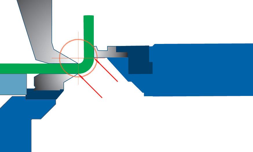
Figure 1—In folding, the distance between the clamping and folding beam contact points is analogous to a V-die opening in a press brake air bending operation. The distance determines the radius and can be adjusted for any material thickness the folding machine is rated to handle. Images courtesy of MetalForming Inc.
The pencil draws the arc length that the folding beam takes. Close the protractor, and you move the moment of bending closer to the pivot point; this results in the folding beam moving in a short arc length and producing a small radius, optimal for thin material. Open the protractor, and you move the moment of bending away from the pivot point; the folding beam swings in a longer arc length and produces a larger radius, optimal for thicker material.
As Prokop explained, “Driving these two axes [that is, these two points of the protractor] simultaneously gives you the ability to go from 30-ga. to 0.25-in. material with no tool change. Changing the gap between the point and pencil [using the folder’s protractor metaphor] is analogous to changing a V-die opening on a press brake. The adjustments go down to four decimal places.”
Making the bend radius this way works up to a point. Make that gap too big, and the radius collapses a bit and becomes egg-shaped. To avoid this, the folder starts to bend incrementally, like bump bending on a press brake (see Figure 2).
To bend incrementally, two tooling surfaces interact: the clamping beam tool and the folding beam tool. The relationship between those surfaces determines the shape of the radius bend.
“For example, say you need to produce a specific radius bend. The machine knows to move the folding beam to a specific angle,” Kennedy explained. “The upper clamping beam moves up, the backgauge moves the part forward, and as the upper clamping beam moves up and down, it forces the material against the folding beam tool to produce the radius.”
“Folding machines do not use the tonnage that press brakes do, so you’re not going to get those indentations [when bump bending],” he added, saying that folding tools also don’t have abrasion points.
“Some large radii look so smooth, they look like they’ve been formed on a roll former,” said Geoff Stone, CEO of MetalForming Inc. For precision work, modern systems adjust parameters based on the material at hand.
“You have to remember that we’re working with sheet metal, and there’s always going to be variability. The intelligence in the system records all the corrections being made when the machine is first implemented,” Stone said.
“The machine learns,” Stone continued. “It understands what the bend allowance should be, and we use that knowledge to create the flat blank dimension.” He added that once that intelligence is in the control, a folder should be able to make a perfect bend on the first part, no tweaking required.
As Prokop explained, the nature of folding—the fact that the machine forms by applying pressure only to the outside surface of the bend—mitigates material variation effects like thickness and tensile differences. It also makes the process well suited to challenging or sensitive material surfaces, including tread plate, perforated and other hole-intensive material, and prepainted material.
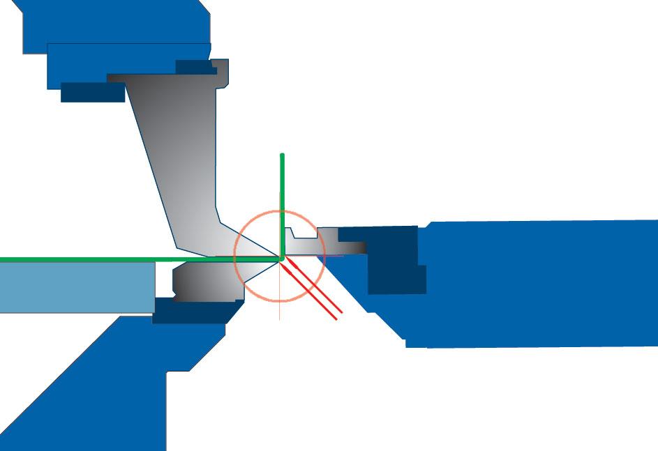
Figure 1—In folding, the distance between the clamping and folding beam contact points is analogous to a V-die opening in a press brake air bending operation. The distance determines the radius and can be adjusted for any material thickness the folding machine is rated to handle. Images courtesy of MetalForming Inc.
Gauging on a Folder
Depending on the size of the part, the operator can insert the part from the front or back (see Figure 3). When in back, the operator often stands by a J- or U-shaped table, with leg of the J or U directly behind the tooling. These shapes make the table long enough to handle long parts but allows the operator to stand close enough to the tools to manipulate and slide the work against the backgauges.
When it comes to gauging, a folder has several reference points. It has backgauge fingers that emerge from the backgauge table; the most conventional way to gauge on a folder, these gauge the back edge of the part. The folder also can reference the front edge of the part.
“The folding beam becomes the gauge point when gauging to the front of the machine,” Prokop said, adding that some systems “have fingers that pop out, creating two gauge points for long parts that lack a straight edge.”
Other fingers also can emerge from the table for gauging off notches or adjacent, previously formed flanges. With the right backgauge setting, folders also can handle tapered parts. “It’s a simple process,” Kennedy said. “The gauge fingers have micrometer barrels on them. You simply adjust the two outside fingers, so they bump against the material at a tapered angle.”
Tooling Options
A folder’s tools can bend any angle and any thickness that the machine is rated for. This doesn’t mean there are no tool changes whatsoever, however. Tool changes usually are needed not because the folder is bending a different material thickness or angle, but instead because it needs to form without colliding with the workpiece.
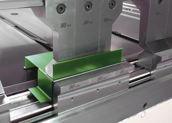
Using segmented clamping tools to form boxes of different lengths and widths is a prime example. Another is a deep clamping beam tool to handle large return flanges (see Figure 4), analogous to a gooseneck punch on a press brake. Yet another example are corner clamping beam tools with wings that extend to the end of a bend, holding the material underneath previously formed return flanges.
An operator running a heavy-duty folding machine might change folding beam tools (though not the clamping beam tools) for folding different thicknesses. Other special folding beam tools can help reach tight areas in return flanges.
The operator could also insert a special segmented folding beam tool that approaches the workpiece from an angle, allowing the folder to form 90-degree internal flanges (see Figure 5).
Because the folding beam tools are segmented, they can access bends in internal cutouts. And because the tools are angled, the folding beam itself need not swing 90 degrees to make a 90-degree angle; this prevents the beam from colliding with the workpiece.
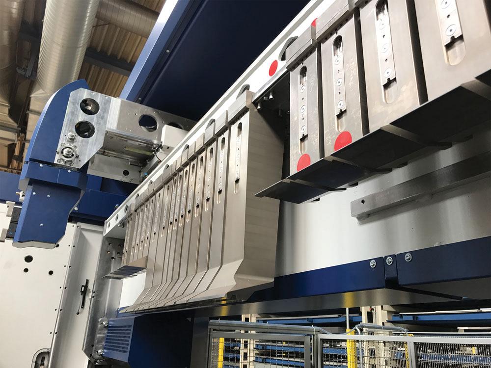
Some folders today can come with automatic tool changes, with mechanized grippers swap ping out the clamping beam tools (see Figure 6). Because some machines form deep boxes, they require tall clamping beam tools, more than 19 in. in some cases. These large tools make automatic tool changing a necessity.
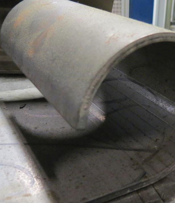
Figure 2—This tight incremental bend in 0.25-in.- thick material was made on a high-thickness capacity folder. The outside surface has only very faint bend lines.
Other machines have rotating upper beams, which add tooling flexibility. “One side of the beam has segmented clamping beam tools for making boxes and other four-sided part geometries; and another side has a conventional clamping beam solid tool for making flanges without adjacent bends,” said Barden, adding that machines also can have segmented box tools on both sides of the clamping beam.
Folding machines also can have segmented clamping tools on both the upper and lower beam. Combine this with a height-adjustable backgauge table, and a folding machine can form complex parts, including those that must be gauged off a previously formed negative (downward) bend (see Figure 7).
In folding, tool changes are the exception rather than the rule. “We don’t change clamping beam tools for thickness or different bend angles,” Stone said. “We’re only changing them for space,” providing clearance for previously formed flanges.
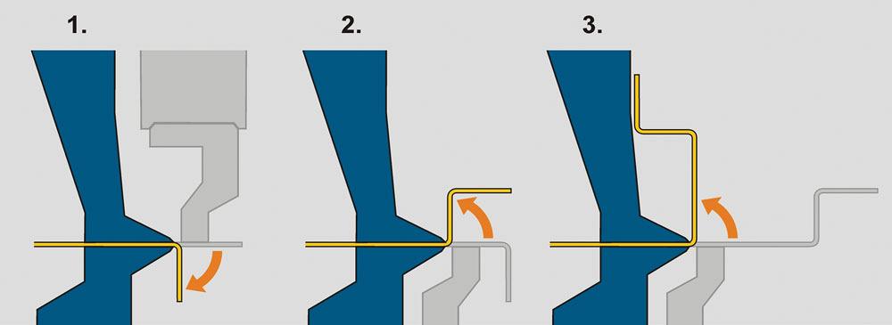
Bidirectional Bending
Another advancement arguably has had a far greater impact in folding than automatic tool changing: the bidirectional, or up-down, folding beam (see Figure 8). Decades ago folding machines’ bending beams swung only upward to create a positive bend. If an operator needed to create a bend in the other direction, he needed to flip the piece. For large pieces this could be time-consuming, and for many it was a major limitation. After all, the primary reason fabricators invested in a folding machine in the first place was to bend large parts.
The act of up and down bending on a folder is far more complicated than it looks. First, the beam must move outward to avoid colliding with previously formed flanges. Second, its pivot point must change so that the edge of the swing beam’s bending tool contacts the outside of the workpiece in the right place, both above and below the workpiece. Thanks in part to precise servomotors and other advancements within the past decade, the modern folding machine can accomplish this feat quite readily, with no manual intervention.
Automation Opportunities
Regarding automation, sources emphasized the need to look not just at the folding speed or part-to-part time, but the entire folding process.
And today’s folding machines have a range of automation possibilities. One is to use vacuums in the backgauge fingers that grasp the part and manoeuvre it from bend to bend on one edge (or one plane) of the part. The machine is programmed to open the clamp, move the part, close the clamp, and perform each bend. The operator need not spend his days constantly hitting a foot switch for each bend and position the part to the backgauge fingers.
“Because the operator is out of the work area and behind a light curtain, the machine does not need to perform its safety stops either, like a pause before the clamping beam pinches the material,” Prokop said. “This speeds the cycle time tremendously.”
Beyond this comes further mechanization and robotics. Some systems integrate robotic arms that lift sheets onto a conveyor that in turn carries the sheets to the backgauge table, at which point a mechanized foot moves the workpiece into position against the backgauges. After one edge is formed, the mechanized foot rotates the workpiece for the next bend. Other systems use a pick-and-place robot to rotate the workpieces and place them against the gauges (see Figure 9).
“If a machine has a part manipulator on it, the sky’s the limit,” Kennedy said. “You can integrate towers, robots, gantry systems, and other automation. Two things drive this: the fabricator’s required product flow and the floor plan.”
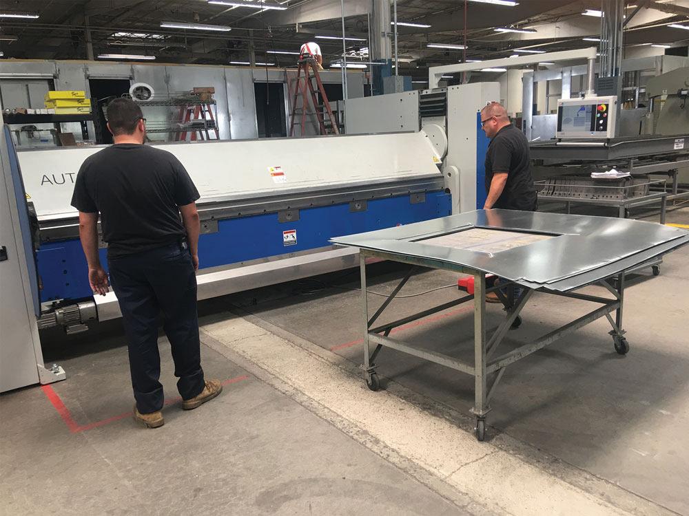
Figure 3—Bending technicians operate a folder from the front. On other machines, an operator stands behind the work area. Photo courtesy of Roper Whitney.
He added that a robot can make sense for the right part mix—say, if it’s lifting and feeding a series of large blanks onto a folder’s backgauge table. “But it’s not always so easy just to adapt a robot to every folding operation. A lot of movement from the robot can actually slow the process down, especially since the folder can move so quickly through small lot sizes.”
“In many cases, shops find it most efficient to use a conveyor to feed the parts to the folder,” Prokop said.
Besides physical automation, automation of information processing has entered the folding arena as well. This includes offline programming and simulation.
“You can now take a CAD file, a STEP file, or a DXF file and convert it into machine language,” Kennedy said. “Essentially, this allows on-machine programming to go by the wayside. A designer can design a part and then look at a simulation of the machine bending the part, so he can know that it can be made on the machine. He can send the part right to the control, and the operator pulls the part number up. The operator may need to tweak it to account for material variability. But for the most part, all the moves the machine needs to know are there.”
Controls overall have become more user friendly.
“Folders have touchscreen controls now where you can program many intricate parts much more quickly than you could years ago,” Smith said.
Finding its Place
A folding machine could never replace a press brake entirely. To be folded, a part requires a flat surface for the clamping beam tools to grasp. And sources did point out that folders have limitations when trying to hem thick material.
As with any other sheet metal bending technology, folding does require that a part have a minimum flange length. A folder typically needs a flange to be at least six times the material thickness, though some machines working on some part geometries can work with flange lengths down to three times material thickness. (Sources emphasized that this is part-dependent.)
When it comes to flexibility, the press brake has major advantages. If a fabricator needs to form a complicated part with uneven surfaces (that is, it wouldn’t lie flat between bends), a press brake may still be the best approach. And aside from a few specialty applications, for thick plate, a high-tonnage press brake is usually the only option.
“You see shops with folding machines sitting next to press brakes, which are sitting next to panel benders,” Prokop said. “Every machine has its place.”
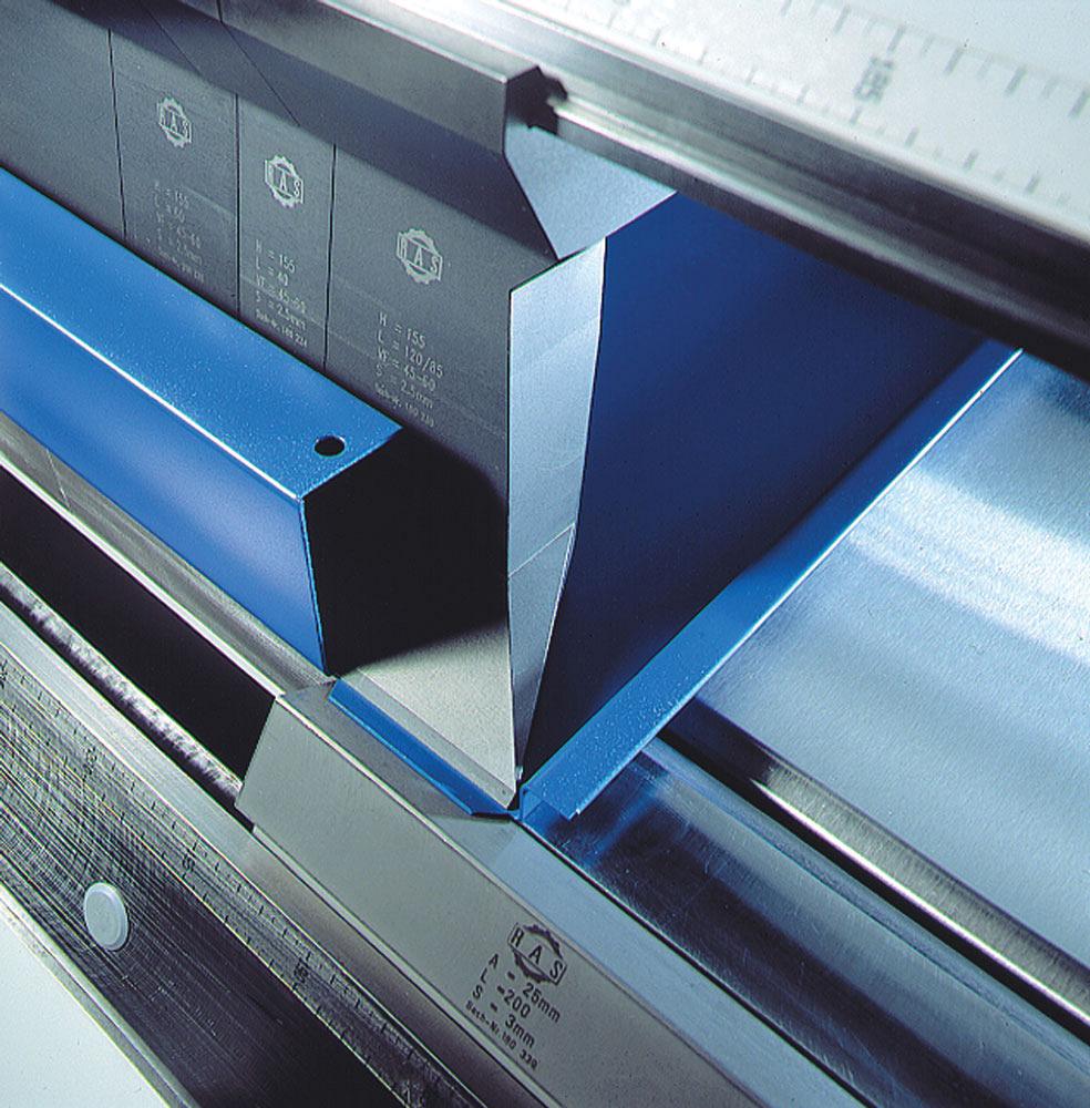
Figure 4—Segmented clamping beam tools provide clearance for adjacent flanges as well as sufficient clearance for the return flange. Image courtesy of RAS Systems.
“Most fabricators have parts that are perfectly suited to run efficiently on the press brake,” Kennedy added, “but then they have some parts that can run so much faster on a folder. The two machines are a perfect marriage, really.”
Every forming option has its pros and cons; it’s the nature of technology in general. But according to sources, when it comes to precision sheet metal forming, the modern fabricator has plenty of choices, and a folding machine is one that shouldn’t be overlooked.
Senior Editor Tim Heston can be reached at timh@thefabricator.com.
Cidan Machinery, www.cidanmachinery-americas.com
MetalForming Inc., www.metalforming-usa.com
RAS Systems LLC, www.ras-systems.com
About the Author

About the Publication
subscribe now


Keep up to date with the latest news, events, and technology for all things metal from our pair of monthly magazines written specifically for Canadian manufacturers!
Start Your Free Subscription- Stay connected from anywhere

Easily access valuable industry resources now with full access to the digital edition of Canadian Metalworking.

Easily access valuable industry resources now with full access to the digital edition of Canadian Fabricating & Welding.
- Trending Articles
1
BlueForge Alliance partners with Nuts, Bolts & Thingamajigs to develop Submarine Manufacturing Camps

2
Portable system becomes hot tech in heat treatment

3
Orbital tube welding webinar to be held April 23

4
Cidan Machinery Metal Expo 2024 to be held in Georgia May 1-2

5
Corrosion-inhibiting coating can be peeled off after use