Senior Application Engineer
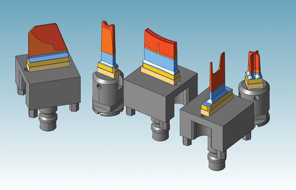
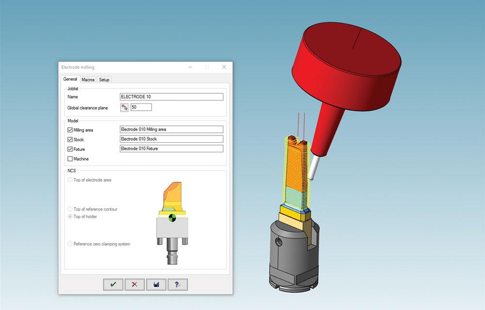
Electrode and holder assemblies are developed using the hyperCAD-S electrode module.
The die-sink EDM process is an important operation in mould creation. After machining, parts are moved to a sinker-style EDM machine for the final, and critically important, part features to be made.
All of the processes involved before this stage, including design, programming, and simulation, must keep pace with production time to keep machines running in step with each other. Electrode design and production also needs to be aligned with these stages to ensure electrodes are on hand and correct to eliminate downtime.
Traditionally, designing an electrode is a time-consuming endeavour.
Identifying geometry requiring die-sink EDM manufacturing, copying said geometry, and creating tangent and linear extensions necessary to clear the electrode holder of any interference with surrounding surfaces are only the beginning stages of electrode design. Problems arise when the extensions are not long enough, which causes the holder to violate the core or cavity surfaces.
At that point it is necessary to re-create longer tangent or linear extensions off the open edges of the pulled electrode geometry to ensure there is no interference.
Using various inherent analysis tools, a CAD system can help identify areas of the core or cavity that require die-sink EDM manufacturing.
Once these areas are identified, intelligent, geometry-based selection of the faces is performed. The electrode geometry is automatically copied, and tangential then linear extensions of the open edges of the pulled geometry are developed without any further input required by the electrode designer.
Finally, the base of the electrode is created and an electrode holder attached.
Modern CAD/CAM systems with dedicated electrode functionality eliminate the necessity of having to re-create electrodes once they have been developed.
Using a database of user-defined electrode holders, the CAD/CAM system automatically selects the correct holder based on the size of the pulled electrode geometry. Because the CAD/CAM system recognizes the entire core or cavity model, it is possible to instruct the system how far above existing geometry the holder should be at its lowest burning position.
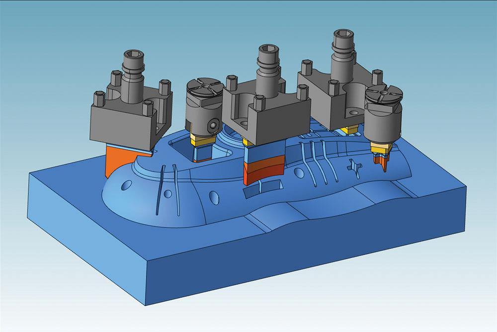
The electrode milling process in Open Mind’s hyperMILL keeps pace with die-sink EDM work to eliminate bottlenecks.
This is done before the automatic tangential/linear surface extension development to ensure that there will be no interference.
A great deal of surface/solid modeling is required when using a CAD/CAM system without a dedicated electrode design and manufacturing module. Electrode geometry must be defined, copied, and then greatly modified to achieve the desired outcome.
Open areas need to be filled, extensions must be created to the base, and holder selection needs to be based on user discretion. Location of the electrode must be exact, and the potential for the input of errors by the user can cause incorrect geometry creation, holder collision, or misaligned coordinates for the final burn location.
These issues can be eliminated by incorporating a dedicated, intelligent electrode design and manufacturing module within the CAD/CAM system.
While designing an electrode can become virtually automatic in a good CAD system, many requirements still may be necessary to bring that electrode design into the manufacturing end of the software.
For this reason, there must be a direct link between the CAD and CAM systems. A single database is necessary to eliminate these requirements. If design and manufacturing are two stand-alone packages, the intelligent link between design and manufacturing is removed.
A single, combined CAD/CAM database allows the designed electrode to be derived from the assembly model and transfers that design into the manufacturing environment, including the required coordinate system for machining. Again, based on a user-defined database, the initial raw stock is automatically selected and incorporated in the manufacturing process.
User-defined macros consisting of a collection of machining cycles based on the specific style of electrode are applied, and the development of the toolpaths required for the machining of the electrode are calculated.
During the design phase of electrode development, the designer inputs the number of electrodes required (rough through finish), the spark gap for each electrode, and the type of burn technology (sink, orbital, widen, linear, or any combination). This pertinent information is transferred to the CAM portion of the software, automatically machining the electrode to the correct shrink rate.
This is achieved through parameter settings for each cycle within the macro. If the spark gap changes for a different job, the cycles are automatically updated based on that information.
Electrodes are checked against the part model to ensure proper length, fit, and shape.
If deemed necessary, full simulation of the manufacturing process, including a model of the CNC machine itself, quickly duplicates what will be output to the CNC machine. Reports can be generated consisting of tool lists, including holder names, tool length, gauge height, and raw stock requirements, and overall machining times.
If a CAD/CAM system correctly and accurately pulls the electrode geometry, develops all required extensions, adds a base, determines the correct holder based on the electrode size, maintains a user-defined clearance distance between the holder and the core or cavity, and then outputs the precise location of that electrode to the EDM machine, is simulation really a necessity?
An intelligent electrode package should eliminate the need for simulation.
After the mould component has been machined and is awaiting the final detail development requiring die-sink EDM, the electrodes need to be ready when that component is. If the EDM department is waiting for electrodes, or the electrode manufacturing department is waiting for the toolpaths, due dates become threatened. There is nothing worse than having to tell a customer that their job is going to be late.
If possible, electrode design and manufacturing can and should be in-process simultaneously with the manufacturing of the mould component itself. Once the mould component is off the CNC machine, the electrodes should be available to finish the job.
With a dedicated electrode design and manufacturing module (called hyperCAD®-S and hyperMILL® at Open Mind), this is easily achievable.
These systems, and those like them, offer all of the tools required to quickly and accurately design an electrode. The ability to identify and quickly select electrode geometry, based on unique selection capabilities, eliminates hours of electrode development. The system creates and tracks the coordinates for each electrode, including any C-axis rotation that can be automatically applied to minimize initial stock size.
A full detailed drawing, including both individual electrode designs and assembly design, is generated at the click of a button.
Any CAM system should offer automated creation of the manufacturing process for each individual electrode. Automated, not automatic. It is always up to the electrode designer/programmer to decide how he wants to machine an electrode; however, once the electrode is machined, that technology then can be applied to any electrode of similar type.
The parameters of the individual cycles change based on the parameters of the electrode being machined, with full user interaction, if desired. The machining coordinate system is created from the assembly model, ensuring the accurate machining of the electrode.
CAM systems should offer 2.5-axis through 5-axis cycles. The system from Open Mind features both Tangent and Tangent Plane machining, utilizing a conical-style barrel end mill, which allows 5-axis machining of tall, thin electrodes such as rib blades.
Of course, these technologies can be applied to the machining of the core or cavity geometry, not just electrodes. Accurate feature recognition helps reduce redundant programming tasks to help expediate the manufacturing process.
Alan Zielinski is senior application engineer, Open Mind Technologies USA, www.openmind-tech.com.


Keep up to date with the latest news, events, and technology for all things metal from our pair of monthly magazines written specifically for Canadian manufacturers!
Start Your Free Subscription
Easily access valuable industry resources now with full access to the digital edition of Canadian Metalworking.

Easily access valuable industry resources now with full access to the digital edition of Canadian Fabricating & Welding.