- FMA
- The Fabricator
- FABTECH
- Canadian Metalworking
Machining Thin Walls and Floors
Proper technique, coolant use are keys to successful milling operation
- By Brian MacNeil
- March 31, 2016
With decades of engineering advances in material strength and designs, engineers are now more able than ever to push the envelope when it comes to weight savings in all forms of transportation, including construction vehicles.
While new techniques offer sound environmental and cost advantages, they often present new challenges for manufacturing.
Incorrectly applying a cutting tool to thin, deep, and lightweight structural sections in a component often induces the kind of heavy chatter that results in damaged tools, components, and machine spindles. Taking advantage of some simple programming and tool tips can go a long way in preventing these issues.
Thin walls are described by their ratio of wall thickness to height. This ratio changes the cutting technique that must be chosen.
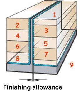
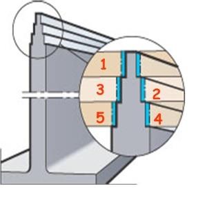
For ratios of less than 30-to-1, use the step support milling technique. This provides overlapping support on opposite sides of the wall. When you alternate the depth of cut from side to side, material is left to support part of the wall for the opposite side (see Figure 1).
At ratios above 30-to-1, employ what often is called a Christmas tree routine. The goal is for the thicker section below to support the thinner sections above. The key is to move down the wall in a stepwise manner, leaving a greater thickness as you move down is key (see Figure 2).
Finishing in either of these scenarios also requires a change in the usual way of thinking. Conventional and climb milling give two very different results based on the chip formation each causes.
Climb milling tends to have a pulling effect, while conventional milling gives more of a pushing action.
Because of this pushing action, choose conventional toolpaths on thins walls. There is less deflection, and better accuracy is maintained, but the possibility of smearing is increased, so coolant is recommended in all materials.
In practical terms, conventional milling has a tendency to cut undersize, while climb milling tends to cut oversize, so take this into consideration for setting tolerances.
Cutting on the Floor
Thin floors also are typically stated as a ratio. When the floor becomes less than 1-to-30 of the pocket’s width or length, it is considered thin. To overcome this, try leaving more material for a finish pass. Leaving as much as 4 mm will keep the base as stable as possible in the finishing process.
Tool selection is critical. The higher the helix on the tool, the more pull it tends to create. This, of course, has a negative effect on the part.
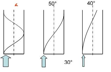
Use indexable milling tools whenever possible because they usually have lower axial cutting forces when compared to solid-carbide tools. If solid-carbide tools are the only option, use one with a low helix angle and the largest possible corner radius. The radius has an opposite effect, creating a chance for equilibrium between the two (see Figure 3).
Brian MacNeil is milling products and application specialist, Sandvik Coromant Canada, 905-826-8900, www.sandvik.coromant.com.
subscribe now


Keep up to date with the latest news, events, and technology for all things metal from our pair of monthly magazines written specifically for Canadian manufacturers!
Start Your Free SubscriptionAbout the Author
- Trending Articles
Automating additive manufacturing

Sustainability Analyzer Tool helps users measure and reduce carbon footprint

GF Machining Solutions names managing director and head of market region North and Central Americas

Mitutoyo updates its end-user portal

Enhance surface finish with high-speed machining

- Industry Events
CTMA Economic Uncertainty: Helping You Navigate Kitchener Seminar
- May 2, 2024
- Kitchener, ON Canada
Automate 2024
- May 6 - 9, 2024
- Chicago, IL
ANCA Open House
- May 7 - 8, 2024
- Wixom, MI
17th annual Joint Open House
- May 8 - 9, 2024
- Oakville and Mississauga, ON Canada
MME Saskatoon
- May 28, 2024
- Saskatoon, SK Canada


