press brake product manager
- FMA
- The Fabricator
- FABTECH
- Canadian Metalworking
Part design and the bending process
Designers and operators need to factor in part design for effective bending practices
- By Steven Lucas
- July 22, 2019
- Article
- Fabricating
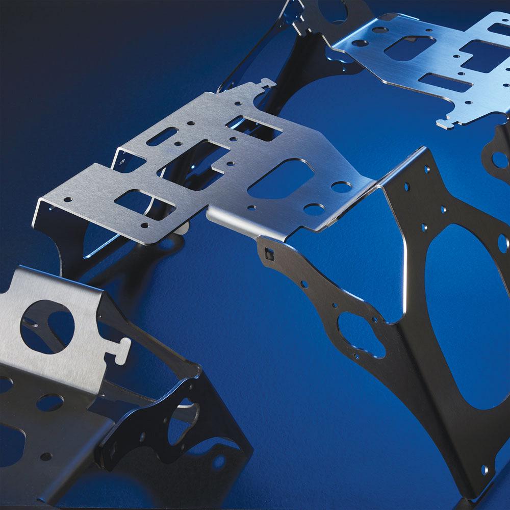
Today designers are creating more complex parts with multiple bends to reduce welding and assembly requirements.
Any designer can come up with a concept or part. However, not all parts are designed to be properly bent. There are many factors and features that both designers and operators need to keep in mind when it comes to part design for efficient bending.
Before the design even starts, a designer must be 100 per cent sure of what is possible on the shop floor. There is no point in starting a design without considering what tools are being used, what functions are allowed based on the tools, and what flanges can be bent (for example, if Z bends are possible). It’s also important to know the length and tonnage of the machine and its features, such as whether the machine includes a backgauge system, automatic crowning, or an angle measurement system, because all of these elements play into how well a part can be bent efficiently.
The operator needs to ensure that he has all of the part information fed from the bending software to the control, such as what tools are need to bend the part and where to position the tools on the machine. Modern press brakes can provide a 3D simulation of the bend program, so the operator will know how to handle the part during the bending process from start to finish.
Avoiding Bending Failures
The most common bending failure occurs when the operator uses the wrong tools. Operators should be familiar with all available tooling and should verify tooling tolerances every time tooling is put onto the machine. They must make sure that the tooling is in good working condition and is within the manufacturer’s specifications. The bending information and instruction will come from offline software directly to the controls, so there is no way to identify if the right tools were put on the machine. It is incumbent on the operator to know what type of bending setup is needed because it is almost impossible to make good parts with bad tooling.
Properly handling the part is also crucial to avoid bending failures. The operator can use a 3D simulation of the bend program to see how to effectively handle the part through the bending process. All of the forming features on a part should be recognized by the offline software, and the simulation will show whether or not those features on the part can be effectively bent or if there may be collisions with the punch or die during the bending process before the machine is actually put into use. If the part can’t be bent without collisions, then a designer may need to reconfigure the part dimensions or displace certain features.
Another common example of part failure is when an operator is bending a symmetrical stainless steel part with protection film. Sometimes operators will start bending the part with the protection film on the wrong side.
Some sheet metal materials should be bent perpendicular to the direction of the metal fibre. When the sheet is bent parallel to the direction of the fibre, cracks are likely to occur, and if the bending strength of the material is low, it is more likely to break at the outside of the bending radius.
Material also plays a big part in bending success or failure. Each material has different bend allowances and inside radius. If this is not factored into the design, operators may find that they will need another unfold part to cut out with a laser or punch machine. If there will be multiple operations, knowing the type of material is crucial before actually creating the unfold part.
Accuracy
The accuracy of the part is a function of the bend allowance and bend deduction. The operator should consider a control that has the bend allowance and deduction intelligence or variance database built in. Bending parameters are automatically controlled by such a database, which stores and cross-references previous bending data history on specific tools and materials. This considers the material type and thickness, the bend angle, V die, angle of the V die, and the punch radius—all of these parameters will influence the bend allowance. Selecting the correct bend allowance ensures part accuracy.
It’s also very important to ensure that the angle is correct. For example, if the operator starts bending a very simple U-profile with very high flanges, if the angle underneath is fluctuating a lot, then the dimension on the top of the profile will also fluctuate. There is a simple way to calculate this so that there is minimal fluctuation: the tang of the tolerance of the angle multiplied by the height of the flange. This formula calculates exactly what the tolerances on the top will be. Having a press brake with an angle measuring system makes this process much simpler and more accurate. With this system manual test bending and correcting are eliminated as is the need to check parts within a batch run, scrap is reduced, and operator involvement is minimized. Most press brake manufacturers offer some form of angle measurement technology.

Before the design even starts, a designer must be 100 per cent sure of what is possible on the shop floor. There is no point in starting a design without considering what tools are being used; what functions are allowed based on the tools; and the length, tonnage, and features of the machine.
Holes
Ensuring hole accuracy can be somewhat tricky and is often the cause of part failure and misalignment, especially when it comes to holes on multiple bends. The more times the sheet metal is bent, the greater the bending tolerance. It can be somewhat difficult to ensure the accuracy of the dimensions of multiple bends, which is why aligning holes in these situations is not easy. One way to minimize misalignment is for designers to avoid strict tolerances on features of multiple-bend parts.
It’s also important to note that if a hole is too close to the bend line, it will be within the deformation zone, which means that this hole will also be deformed.
Handling
If an operator is bending a large part that is difficult to handle, performing a bend on the maximum length of the part will strengthen the panel, giving it rigidity to make it easier for the operator to handle.
If this is not possible, some operators use the forming features of a punch machine to strengthen inside the Z-profile, which also makes the part stronger.
Machine options such as programmable sheet followers and front supports also help the operator manage large parts. Programmable sheet supports follow the part at a speed that is 100 per cent synchronized with the beam of the machine.
Automation
One of the big trends is bending automation. Increasingly, fabricators are considering the use of robots in bending applications. Designers need to be aware of who will be bending the parts, as a part bent by an operator may not be able to be handled by a robot. The design of the part needs to be adjusted depending on who will be doing the bending. An operator is able to move things in a way that a robot with grippers may not. For example, if a part has a lot of holes inside, the gripper may not have a solid hold of the part.
Software
Today’s software is making it easier for designers to create parts that can be bent correctly. They are no longer required to focus on creating an unfold part with all the dimensions. The software can develop the correct unfold part based on the model, assign the correct bend allowance and bend deduction, send it to the laser machine to cut out, and then it can go directly to the press brake for bending.
Some designers still want to spend time in this phase, but advanced software is making it easier for them and removes the human error. Designers are able to create a part and plug it into the software to see if it is possible to bend. If there is a failure or collision, they can make adjustments to work around this instead of having to buy new tools or forward the problem onto the shop floor.
Today designers are creating more complex parts with multiple bends to reduce welding and assembly requirements. Instead of creating two or three parts that need to be joined together, designers are pushing the limits and creating complex parts that include all features in one.
Steven Lucas is the press brake product manager for LVD Company, Belgium. U.S. headquarters: 12975 Clarence Center Road, Akron, NY 14001, 800-828-1527, www.lvdgroup.com.About the Author
subscribe now

Keep up to date with the latest news, events, and technology for all things metal from our pair of monthly magazines written specifically for Canadian manufacturers!
Start Your Free Subscription- Industry Events
MME Saskatoon
- May 28, 2024
- Saskatoon, SK Canada
CME's Health & Safety Symposium for Manufacturers
- May 29, 2024
- Mississauga, ON Canada
DiPaolo Machine Tools Open House 2024
- June 4 - 5, 2024
- Mississauga, ON Canada
FABTECH Canada
- June 11 - 13, 2024
- Toronto, ON Canada
Zoller Open House & Technology Days 2024
- June 12 - 13, 2024
- Ann Arbor, MI


