


Senior Customer Training Instructor
The following article is a summary of the experience of Duane K. Miller and the late Omer W. Blodgett dealing with distortion over the course of their careers at the Lincoln Electric Co. Distortion control, as well as other arc welding topics, are covered in more detail in the Blodgett Design Seminars hosted by The Lincoln Electric Co. several times a year in Cleveland, Ohio.
Part II will appear in the September issue.
Distortion, which is an alteration to the original shape of something, should be considered when designing and fabricating a welded assembly. Some welding codes require a distortion control plan where excessive distortion or shrinkage could occur. While distortion cannot be eliminated completely, implementing the 18 principles suggested in this two-part article can help minimize unwanted distortion to an acceptable level.
Distortion in a weldment results from two factors that occur during arc welding. First, hot and solid weld metal shrinks and pulls the base metal as it cools. Second, a portion of the base metal surrounding the weld is locally heated and expands, upsets, and subsequently shrinks. In both cases, shrinkage (straining) occurs in the longitudinal, transverse, and through-thickness directions, resulting in stresses that cause flexible members to distort. The more flexible the member, the more movement occurs. Accordingly, thin members have a greater propensity to distort than thicker members. However, thicker members have a greater susceptibility to cracking because they are less flexible and do not distort as much. The total amount of distortion can be completely elastic or have an elastic component and a plastic (or inelastic) component. The distinction between the two components will be discussed in more detail later.
There are several types of distortion.
Angular distortion is caused by non-uniform transverse shrinkage of the solidified weld. A common type of angular distortion occurs with double-sided fillet welds in T-joints (Figure 1) and single-sided groove welds in butt joints (Figure 2). As the solidified weld metal cools and shrinks, the greatest contraction occurs where more weld material is located.
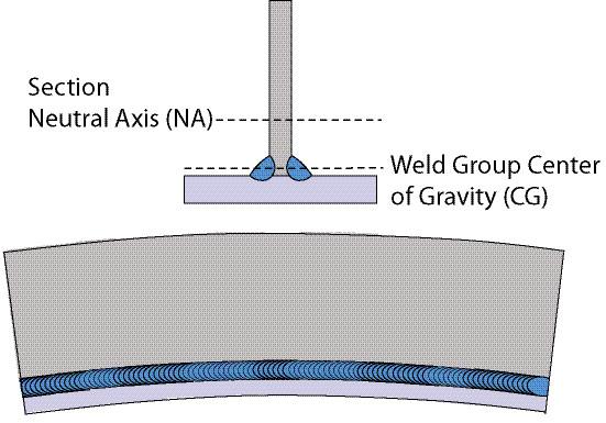
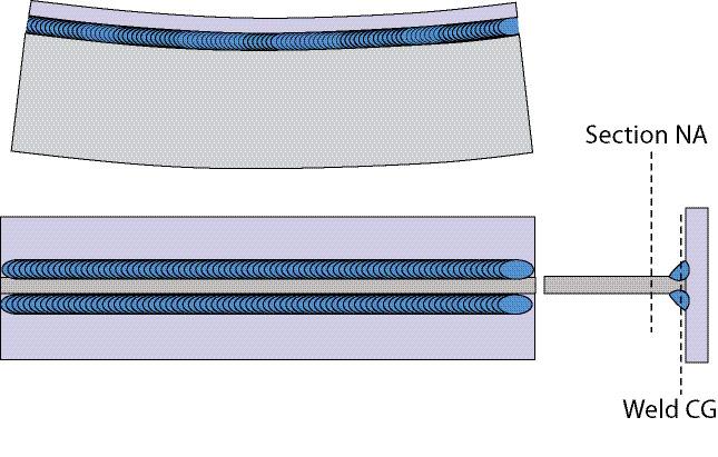
Longitudinal shrinkage occurs along the length of a member. A common example of longitudinal shrinkage is plate girders. Because of the weld along the web/flange interface, the girder length contracts as the weld cools. Depending on the placement of the weld group center of gravity (CG) with regard to cross-section neutral axis (NA), camber or sweep, or a combination of both, can occur. Figure 3 shows camber because the section compresses on the weld group CG side of the NA, about the strong axis. Sweep is like camber except that the distortion occurs about the weak axis of the steel section (Figure 4). Circumferential shrinkage is a form of longitudinal shrinkage in which the weld contracts around the perimeter of a member like a tube and contracts its circumference.
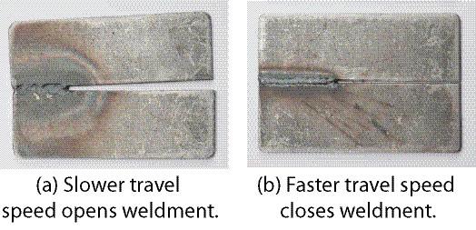
Rotational distortion occurs in butt joints where welding plate edges together and the plates either open or close and cross over each other in approximately the same plane. Whether the plates open or close mainly depends on the travel speed. Slower moving speeds tend to cause opening, while faster speeds tend to cause closing (see Figure 5).
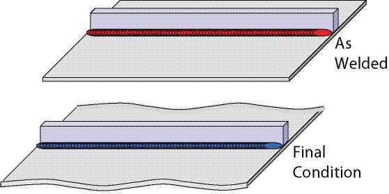
Panel distortion (Figure 6) occurs when a stiffener is welded to a relatively thin panel, causing the panel to distort in the out-of-plane direction. Buckling or warpage can occur when a longitudinal weld is made along a relatively thin plate. The thin plate can buckle or warp in the out-of-plane direction.
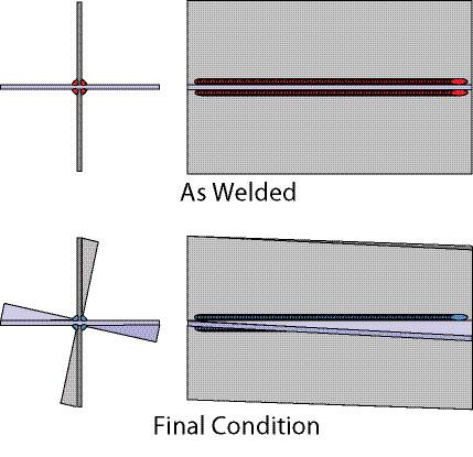
Twisting distortion occurs when the cross-section twists about its centroid. This type of distortion is most common in open sections such as C-shape and cruciform sections that have limited resistance to torsion. An example of twisting distortion can be seen in Figure 7 that shows a cruciform joint.
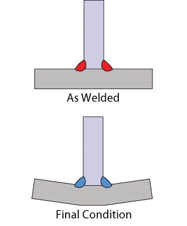
Figure 1 - Angular distortion, double-sided fillet welds in a T-joint.
In this two-part article we will cover 18 principles that can help minimize distortion in welded assemblies and could be used for a distortion control program. We classify the principles into five broad categories: Minimize the creation of shrinkage forces, place the weld where the shrinkage does not matter, maximize the resistance to shrinkage forces, counterbalance the shrinkage forces, and reduce the shrinkage forces. Part I covers the first two categories.
Minimize the Creation of Shrinkage Forces
1. Do not overweld. Minimize the volume of weld metal, but do not reduce the weld size below design requirements. Distortion control starts with the designer. He or she should design the weld using the smallest possible weld size. The fabricator should make the weld no larger than that detailed by the design engineer. Reducing weld metal is a good idea to control distortion and reduce cost.
One way to reduce weld volume is to consider using intermittent instead ofcontinuous fillet welds. For groove welds, consider the various types of preparation and the corresponding volumetric calculations. For example, for relatively thin material (less than about 25 mm) with single bevel groove welds, a larger included angle with a smaller root opening gives a smaller volume. For thicker materials, a smaller included angle and larger root opening produces a smaller volume.
An often overlooked situation in which weld volume is unknowingly increased arises when using pre-qualified details. Using the "As Detailed" and "As Fit-Up" dimensions can significantly increase weld volume, and these dimensions should be minimized as much as possible by using good design, fabrication, and erection practices. Communication among all involved parties can help alleviate the need for using excessive As Fit-Up dimensions during construction.
During fabrication, watch for excessive weld metal removed during backgouging. Weld and base metal is removed from a joint using air arc gouging at a rate of 10to 20 times at which it can be deposited. It is easy for an operator to excessively backgouge a joint, which will require much more weld metal to be filled than necessary. Backgouging should be done with as much attention as possible, using a grinder if need be for more precision, especially in the final stages of preparing the backgouged joint.
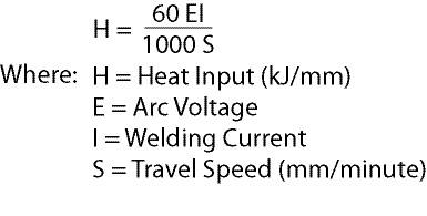
2. Minimize the heat input for a given weld size. Heat input is a mathematical estimation (see equation, Figure 8) of how much electrical energy from the arc is converted into thermal energy in the weldment. This equation is an estimation because some of the electrical energy from the arc is not converted to heat, but rather into other things like sound, light, and smoke generation. Heat input is generally proportional to the cross-sectional area of a weld. Larger welds typically require more heat input. For the same weld size, those welds made with a lower heat input will undergo less distortion because less thermal energy is delivered to the weld and surrounding base metal.
3. Minimize the number of weld passes for a given weld size. With multipass welds it is better to use largerpasses because there are fewer heating and cooling cycles. The initial larger passes "lock in" the plates being welded, and distortion from subsequent passes is better resisted by these locked-in plates. Using more passes with smaller welds leads to a similar cumulative heat input compared to fewer passes with larger pass sizes; however, the smaller passes do not provide such resistance, leading to more angular distortion.
4. Draw the heat away. When setting up an assembly for welding, consider using copper clamps or chill bars. The copper should have direct contact with the base metal as close as possible to the weld to draw heat away from the base metal. Drawing the heat into the copper means that less energy is delivered to the weld joint and thus there is less distortion.
5. Preheat to reduce localized expansion. It may sound counterintuitive to control distortion by adding thermal energy in the form of preheat, but preheat can reduce the localized shrinkage. A preheated part can expand and contract more uniformly, causing less distortion.
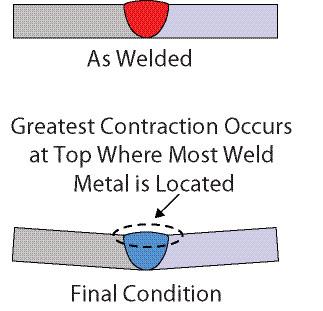
Figure 2 - Angular distortion, single-sided groove weld in a butt joint.
Place Welds Where the Shrinkage Does Not Matter
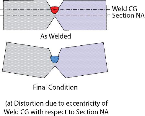
6. Place the weld on the neutral axis (NA). When a weld cross-section aligns with the NA of the piece being welded, it will not experience angular distortion. An example of this applied can be seen with the double-sided V-groove weld shown in Figure 9a. The root pass of an unclamped, symmetrically prepared joint will cause distortion because of the eccentricity of the root pass from the NA of the piece. With some calculations, a non-symmetrical joint configuration can be devised (Figure 9b) that aligns the cross-section area of the root pass with the NA of the piece. The root pass in this case will not cause angular distortion. Further, it "locks in" the piece to the desired position, and subsequent passes can be balanced on either side of the part to keep it straight.
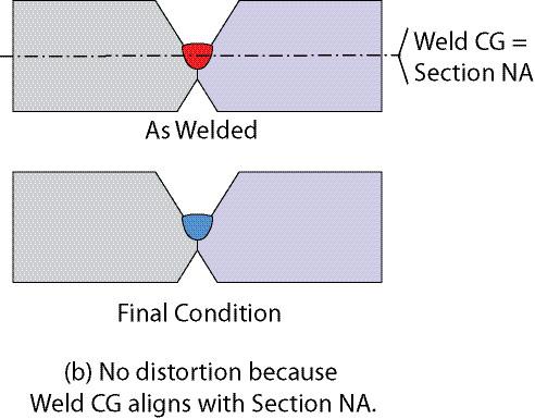
7. Preset to offset distortion. Before welding, members can be preset in a way that is opposite of the expected distortion. Then, when distortion occurs, the member distorts into the desired configuration. Figure 10a shows a single-sided V-groove weld. In the final condition, the distortion produces approximately 9 degrees of angular distortion. Figure 10b shows plates preset with a 9-degree downward angular offset before welding. When the weld metal is deposited, the plates rotate upward so that the final product is straight.
In both of these examples, the same included angle was used. In this case, the bevel angles of the plates have to be adjusted to maintain the 45-degree included angle. The implication of this principle is that some experimentation would need to be conducted to fine-tune the joint preparation for success.
Next month we consider how to maximize the resistance to shrinkage forces, counterbalance the shrinkage forces, and reduce the shrinkage forces.
Duane K. Miller is manager of engineering services, Curtis L. Decker is senior design consultant, and Charlie Cross is senior customer training instructor at The Lincoln Electric Co., 22801 St. Clair Ave., Cleveland, Ohio 44117, 216-481-8100, www.lincolnelectric.com.


Keep up to date with the latest news, events, and technology for all things metal from our pair of monthly magazines written specifically for Canadian manufacturers!
Start Your Free Subscription
Easily access valuable industry resources now with full access to the digital edition of Canadian Metalworking.

Easily access valuable industry resources now with full access to the digital edition of Canadian Fabricating & Welding.


