


Changing the Way We Think About Deburring
Installing a robotic deburring system can reduce media costs, improve part-to-part consistency
Automation has entered the world of manufacturing in a major way. No longer is this mechanization associated only with automotive assemblers or large manufacturers with part runs in the millions.
Nearly every operation now can be automated, included deburring.
CIM—Canadian Industrial Machinery asked John Sockman, director of industrial production for Weiler Corp., to discuss when robotic deburring should be used and how to select end-of-arm tooling. Here is what he had to say.
CIM: What factors are driving the need for robotic deburring?
Sockman: Five key factors shape manufacturer’s demand for deburring automation:
- Reduced direct labor content saves operating costs. This is typically done by producing more parts per shift, running multiple deburr cells with a single operator and increasing uptime.
- Process automation facilitates improved part-to-part consistency. Achieving tight tolerances on edge radius specifications is difficult with a manual process. In addition, the latest in-process inspection technology facilitates automation of part inspection.
- Fewer repetitive motion disorder claims. One of the most common workers’ compensation claim types relates to repetitive motion disorders (RMDs). Manual deburring is a common cause of carpal tunnel and similar RMDs.
- Surface finish refinement can be achieved simultaneously with deburring in many situations. For parts requiring a finer finish than the upstream machining process can produce, deburring automation can reduce overall processing time.
- Reduced media costs. Because of the robot’s strength, accuracy, and speed, media costs can sometimes be reduced by more than 50 percent.
CIM: What role does end-of-arm tooling play in the overall process?
Sockman: Two types of robotic deburring cells are common.
Robots typically process small parts by gripping them and then manipulating them in the deburring media. In this case, end-of-arm tooling involves grippers that can accommodate the different parts the cell will process. For highly complicated parts, grippers often need to be changed at part changeover.
Recent advances in motion control technology have led to the development of force-torque sensors that can provide real-time feedback to the controller about the process. As this new technology develops, it will facilitate improved management of media wear as well as process monitoring. In some cases, it is necessary to regrip the part being deburred to expose the opposite end, which the robot itself can do without operator intervention.
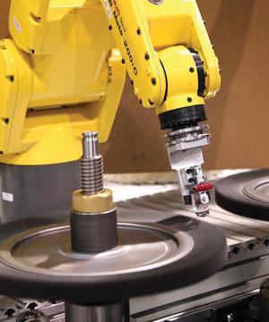
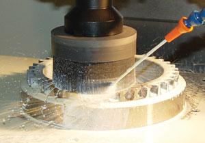
Large parts are typically fixtured while the robot delivers various media to targeted part edges. Such systems are commonly equipped with a tool changer that contains a variety of different tools and media that have been selected for the process.
In these systems, end-of-arm tooling needs to accommodate air, data, and electric lines and must be able to be changed frequently. Finally, tools must be carefully matched to the needs of the media that they will run. If a media is not used at the appropriate speed and power, even the best-designed system will not perform properly. In some cases, it is necessary to refixture the part to expose the opposite end, which usually requires an operator to do so manually.
CIM: How do you choose the correct tool?
Sockman: Tool selection is based on many considerations, burr size being one of the more important. Weiler has a burr classification system to help customers think about how burr size varies with upstream processes. Also, the geometry of the burr — its location on the part relative to the spindle position — has a major impact on tool selection.
Understanding the manual process (grits, surface speeds, media-part orientation) gives excellent insights into the operational requirements of the robot.
Part geometry, the configuration of workholding, and the sequencing of upstream machining processes will determine the position of the burr and whether it can be removed.
Work material also factors into tool selection. Stainless steel and nodular iron are examples of materials that are difficult to deburr. The deburring tool requires more aggression and cycle time than is required to deburr aluminum or cast iron. It is important to design the deburring automation process to have a slightly shorter cycle time than the upstream and downstream processes.
Finally, surface finish, edge finish, and edge radius nominal and tolerance specifications must be considered when selecting a deburring tool. Since the upstream machining process will always vary with cutting tool wear, the deburring tool and process must be sufficiently robust to accommodate this variation.
CIM: How have these tools changed recently?
Sockman: The two biggest changes in system capability have been driven by vision technology and motion control capability. These are the technologies that allow a robot to “see” and “feel.”
New vision systems enable in-process inspection. They also facilitate random part flow so it is no longer necessary to process parts in batches. Parts from different batches with different dimensions can be fed into a cell that uses vision technology to identify the part and pick appropriate tooling and programming based on the part it receives. In the most extreme case, parts with different dimensions can flow to a cell randomly oriented on a conveyor.
The latest force-torque sensors provide real-time feedback on the forces that the part is experiencing. This data can be used to make in-process adjustments for media wear and other process variables.
As software is developed to integrate the latest capabilities of vision systems and motion controllers, the industry will achieve the long-held objective of “adaptive finishing” in which the robot will be able to make adjustments for incoming part condition and media wear based on what it “sees and feels” on a real-time basis.
CIM: How do robotic systems ensure the proper amount of material is removed?
Sockman: There are three categories of process control systems:
- Fully automated, in-process inspection systems are often integrated into deburring automation systems for the aerospace market. This type uses the latest vision systems to inspect critical part features and determine if a part meets specifications.
- CMM-style part inspection can be done offline to meet many manufacturers’ process control requirements. Unlike the inspections described previously, these are commonly used during process setup and at predefined intervals throughout a production run to ensure the process is operating within specification. This type of inspection is common in industries that run large volumes of parts or have tight edge radius specifications, like the automotive and cutting tool industries.
- For most machine shops, which need to meet a print specification that calls for a part to be “burr-free,” a visual inspection by the operator is normally sufficient.
CIM: How are the necessary finishes created in automated systems?
Sockman: The best way to start designing an automation system is to study the manual process that it will replace. It is rarely a good idea to replicate a manual finishing process with a robot because the advantages of robotic processing will not be captured. However, understanding the manual process (grits, surface speeds, media-part orientation) gives excellent insights into the operational requirements of the robot.
subscribe now


Keep up to date with the latest news, events, and technology for all things metal from our pair of monthly magazines written specifically for Canadian manufacturers!
Start Your Free Subscription- Stay connected from anywhere

Easily access valuable industry resources now with full access to the digital edition of Canadian Metalworking.

Easily access valuable industry resources now with full access to the digital edition of Canadian Fabricating & Welding.
- Trending Articles