


Reducing Vibration in Deep Boring
Boring bar selection, including antivibration systems, insert macro- and microgeometries, and proper coolant use all play key roles in boring deep cuts
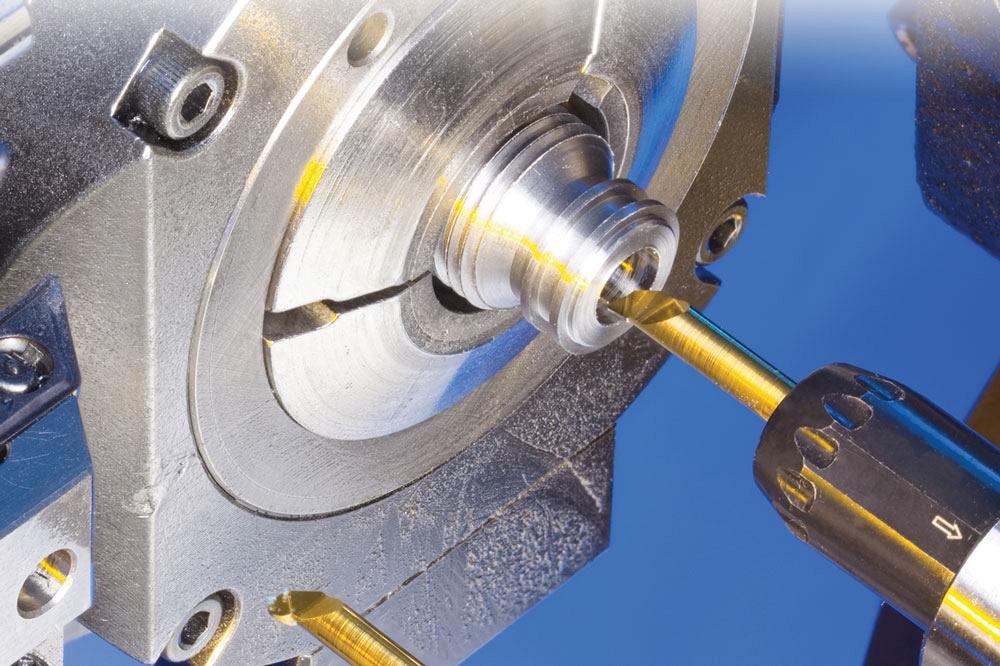
Boring requires a stable setup to combat vibration, which can significantly reduce tool life and productivity. Photo courtesy of Iscar Tools.
The most common application for boring is the enlarging of a drilled hole, which often includes other operations such as facing, chamfering, grooving, and threading.
Precision bores appear in numerous components in the aerospace, heavy construction, and mining sectors. Like any machining operation, these bores must meet their specified tolerances. However, the downside of boring is that it often can be a costly and time-consuming part of the manufacturing process.
Also, mistakes made during the initial drilling process can add unnecessary time to the boring operation and, therefore, costs in both manpower and consumables.
Drill Deep First
Long, deep boring is a complex operation because it starts as deep drilling, which means using long, deep drills and holding tolerances during that operation. Machinists must pay attention not only to how much material is left from the drilling operation that the boring tool needs to remove, but also maintain hole quality. This is because the boring tool will follow the path of the drill—but not as much as something like a reamer would—and you don’t want to have to change the depth of cut if the drill wandered.
“You want to maintain a stable DOC throughout the cut; you don’t want variation,” explained Steve Geisel, senior product manager for Iscar Canada. “If you don’t have a constant DOC, you have to program a taper into the machine.”
Changing the DOC also affects chip creation and surface finish which, when added to longer programming times, can decrease productivity. A varying DOC inside a bore also reduces tool life.
Before Boring
Before the boring bar enters the part, proper clamping needs to be applied.
Clamping stability and a correct center height are two important factors in achieving the dimensional tolerances and surface finish requirements of any component.
“When machining with long overhangs, correct clamping cannot be overvalued,” said Geisel. “If the hole is relatively shallow, you can clamp on the flats that are milled on the shank. But when you start getting into deep boring, most machinists will move away from boring bars with these flats on them to boring bars with cylindrical shanks. These types of bars are held with more clamping contact and are more rigid.”
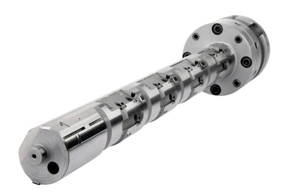
An asymmetric line boring tool can increase process speeds while reducing tool maintenance and handling. Photo courtesy of Kennametal.
Boring bars without milled flats result in more rigidity in the bar because material hasn’t been removed from its length.
According to Geisel, it’s normal for a boring bar to be clamped with set screws on top and bottom for shallow depths. But as bores get deeper and overhangs longer, another type of clamping system should be used. At this time a collet-style clamping system can be used that holds the bar all around its diameter.
“Hole diameter and depth are going to dictate what type of clamping system is necessary,” said Geisel.
The deeper you go into a bore, the more rigidity plays a factor because the bar is sticking out farther. Also, the bar is only going to be as strong as the weakest part of the connection.
“You want to make sure that right from the turret to the insert tip that you have the maximum rigidity,” said Geisel. “By employing the most rigid setup possible, vibration, even in long depth-to-diameter bores, is minimized.”
By reducing vibration you increase tool life, improve surface finish, and allow the best possible cutting data to be used.
“Vibration is definitely something you want to remove from the process in boring, and one way to do that is by having the most rigid setup possible,” said Geisel.
The Bars
Many types of boring bars are available on the market, with each having a set of working ranges. Generally speaking, steel bars are suitable for the l-to-d range up to 4xD, heavy bars such as tungsten to about 6 or 7xD, and carbide bars to 7 to 8xD, but at any point beyond that it’s probably time to consider an antivibration bar.
Going Deep
Sandvik Coromant Canada’s line of Silent Tools® is one example of a boring system designed to minimize vibration with a dampening system inside the tool body.
According to Kevin Burton, product specialist for Sandvik Coromant Canada, great productivity increases and surface quality improvements can be gained, even for shorter overhangs.
“It is not possible to avoid vibration entirely in metal cutting operations, but there are various ways of reducing it,” said Burton.
Vibration often is the limiting factor in getting the most out of a machine too. It requires a reduction in the cutting data. According to Burton, by using an antivibration bar, a machinist can increase the cutting parameters and at the same time get a more secure and vibration-free process with close tolerances, good surface, and much higher metal removal rate, which in summary gives you a lower cost per component.
Inside a dampened tool is a pretuned dampening system that consists of a heavy mass supported by rubber spring elements. Oil is added to increase the dampening.
The size of the bar is important too.
It’s good practice to employ the largest-diameter boring bar you can and assume that the insert is going to do its job and get the chip control you need. The insert’s chip breaker and other geometry features, when combined with the correct cutting data and coolant usage, will produce small, manageable chips that can slide easily past the bar.
“By using a large-diameter bar it will be as rigid as possible, and machining is all about rigidity,” said Geisel.
Combat Forces
Reducing cutting forces is important in long overhangs, something found in a boring operation that doesn’t exist in external turning because the tool is very far away from the turret.
“In these situations we use inserts with small angles. By using inserts with smaller angles, you reduce the cutting forces on the workpiece and on the toolholder,” said Geisel.
It’s also advisable to use inserts designed for boring and not turning. A tougher grade that is not as hard as one used for an external turning operation should be used because not only is there a possibility of recutting chips, but slower cutting parameters are used, which means less heat is generated.
It also is recommended that the insert’s nose radius be used as the basis for the DOC. This is because when the chipformers are built into the insert, they do not start until after the nose radius. Using the nose radius as the DOC gives the chip a place to form—on the chipbreaker, where it belongs.
Boring is a slower operation than external turning and the cutting parameters will reflect that.
“In external turning the part itself falls away from the insert and the chips also fall away. During internal work, the part is always falling into the insert and the chips can be contained in the bore until they fall out the front of the part by coolant backpressure or through centrifugal force. These conditions mean that you will not run the same parameters as with external turning,” said Geisel.
Choosing the correct tool is important to achieve the best possible productivity and results, but it must be run with the correct cutting data and at the correct temperature. Each tool always has an optimized zone.
Coolant Use
“Two things are important about coolant in boring: coolant volume and coolant pressure,” said Geisel. “You have to have enough of both to ensure proper chip formation and evacuation. Unless you are creating a through-bore where the chips can just exit the end of the bore, it’s extremely important to create small chips and get them away from the work zone quickly.”
subscribe now


Keep up to date with the latest news, events, and technology for all things metal from our pair of monthly magazines written specifically for Canadian manufacturers!
Start Your Free Subscription- Stay connected from anywhere

Easily access valuable industry resources now with full access to the digital edition of Canadian Metalworking.

Easily access valuable industry resources now with full access to the digital edition of Canadian Fabricating & Welding.
- Trending Articles