


The Simulation Game
Machine simulation eliminates waste, finds errors before they occur
Machine simulation provides information for the programmer and operator before the program is run on the CNC machine, eliminating errors before they happen live.
Editor’s Note: This article is adapted from the white paper “CAD/CAM & the Benefits of CNC Machine Simulation,” BobCAD-CAM.
While CAD/CAM software has offered users a variety of design and CNC programming benefits for many years, the aspect of simulation has steadily advanced over the past decade to become a critical part of offline programming.
Simulation provides the necessary functions that help eliminate costly programming mistakes at the machine. Many of these benefits are the result of improvements in computer hardware, graphics capabilities, and the fact that simulation functions in CAM software products have improved in recent years. Simulation technolo
gy is now more accessible and affordable than ever.
So why should shops with CNC equipment insist that they have machine simulation? Here are some of the main reasons. You can:
- Proof out the cut paths of your program before physically machining the part.
- Set machine travel limits and detect overtravels.
- Check for errors on the part, including machine, tool, and toolholder collisions.
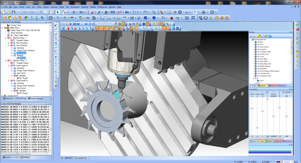
- Utilize your machine’s actual kinematics to visually see your machine tool in action prior to cutting metal.
- See exactly how the finished part will look cut on your machine in a virtual environment.
- Set up an unlimited amount of machines that are accurate to the actual machines in your shop.
- Calculate machine cycle time for every part program.
- Inspect the process with dynamic viewing functionality.
- With machined part deviation, see where tools were unable to machine within the associated operations.
In addition to these capabilities, you will eliminate waste because you no longer will have to scrap parts because of programming errors. It really is about having peace of mind.
Machined Part Deviation
Software that has the machined part deviation function creates a diagnostic tool that allows you to define tolerance ranges for part deviation and display them on the cut model. The simulation analysis lets you to set colours for different deviation tolerances, allowing you to see exactly where leftover material will be not only for milling toolpaths, but for drilling operations as well.
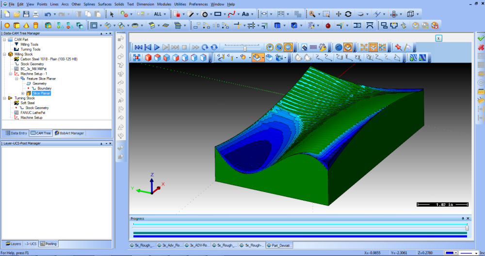
Simulation deviation analysis lets you to set colours for different deviation tolerances, allowing you to see exactly where leftover material will be along the toolpath.
As the toolpath is simulated the different colours -- representing deviations – become visible and these deviations also are listed in the deviation analysis tab. This type of analysis helps you determine surface finishes, and also find areas where stock may remain because a tool is too large to fit in a certain area.
This function eliminates guesswork and can allow you to work more efficiently.
Another function of simulation is multi-tolerance deviation analysis. This is where all of the changes in tolerance are displayed during simulation for analysis. Variations typically are represented in greens and blues, but deviation tolerances can be set to different colours for easy visualization.
Deviation analysis shows where a cutting tool did not go before you actually run the program on the CNC machine.
This helps you in two main ways. First, it helps in properly selecting and setting up the toolpath for finishing operations, and second, it helps you select tools for the entire program.
You can easily see where the deviations are in the program, the entire cutting operation, and which tool was being used by the program. All of this is valuable data when the operator is inspecting the operation.
Advanced Machine Simulation
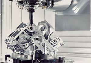
Today’s advanced machine simulation tools even allow you to use your machines’ actual kinematics to simulate the machine’s motion as well as the toolpath.
The process starts by “creating” the machine in the software. This entails defining each element of the machine, such as the linear and rotary axes, and then setting the parameters for each element of the machine, such as the moving direction and limits. These parameter values are used to create posted NC programs. For each element, geometry (.STL) files are added to define what appears in the simulation window.
A structure or “machine tree” is built from the machine’s elements. For any machine configuration, you can think of the machine as having a base, which is the foundation upon which the machine is built.
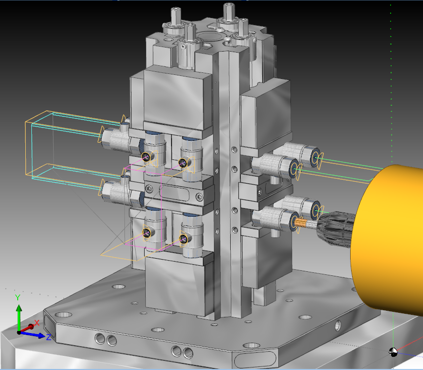
Complex workholding such as tombstones can be added to the simulation to ensure the tool will not crash during operation.
Every machine element is then attached to the base or to some other machine element. The relationship among all of the machine elements, how they are connected, and in which way they move, defines how the machine is built.
Once the data is input into the software, machine simulation is possible, giving the operator everything he or she would need to fully view the CNC machine tool in action.
Machine simulation also provides dynamic viewing features. By changing the machine housing view, you can see the machine tool in different modes, including solid and translucent and off/hide.
Simulation can take place in any view the operator requires so that everything can be analyzed.
In the end, machine simulation features provide a vast amount of information for the operator before the program is run on the CNC machine, making it a valuable tool for any shop.
Chris Corbell is vice president of marketing, BobCAD-CAM Inc., 877-262-2231, www.bobcad.com.
About the Author
About the Publication

subscribe now


Keep up to date with the latest news, events, and technology for all things metal from our pair of monthly magazines written specifically for Canadian manufacturers!
Start Your Free Subscription- Stay connected from anywhere

Easily access valuable industry resources now with full access to the digital edition of Canadian Metalworking.

Easily access valuable industry resources now with full access to the digital edition of Canadian Fabricating & Welding.