


Division Manager
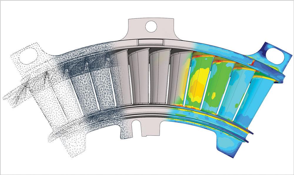
Scanned data includes points and point clouds, triangles forming a “skin” on the part, and coloured zones indicated variation from the CAD model.
Reverse engineering is a familiar task in many job shops.
The process involves measurement and re-creation or repair of existing parts without CAD files or even drawings. New technology can help in completing this complex assignment. Here’s how.
The first step in the process is understanding how the scan will be used.
After being in the 3-D scanning service industry for more than 18 years, I find significant value in asking this simple question: What is the image for? Here’s why.
When approaching a project of any magnitude, the ideal goal is to find the cleanest, clearest path to the optimal desired result. Not knowing the intended output can send a service tech down a very long, inefficient path.
A scenario encountered on a regular basis is a customer’s request for a scan of an entire vehicle engine with CAD output. At face value, we can jump to the conclusion that they need every nook and cranny digitally captured by any medium of my choosing and we can spend several weeks meticulously creating detailed models of starter motors, cooling lines, and complex engine block castings.
However, 99 per cent of the time, all of that work is unnecessary. After you know how the data will be used, a simple volumetric representation is all that is needed to determine fit and clearances. This can be accomplished quickly and efficiently, using simplified scanning techniques and rapid solid modelling.
You also should ask if the customer anticipates changes. If future changes are needed, the method of data collection and creation can change.
One common mistake customers make is asking for a parametric IGES or STEP file. This is a contradiction. Parametric CAD models contain design intent, a structured combination of prismatic 3-D features driven by specific dimensions. IGES and STEP output is a stripped version of that parametric 3-D CAD model, typically represented by that outside “skin” of the CAD surface, allowing users to share 3-D data between multiple platforms that do not share a common internal language.
Knowing what changes may be needed at a later date is important because you can then design a part to make those anticipated areas easier to modify without fighting unwieldy surfaces, fillets, or draft in the completed CAD model.
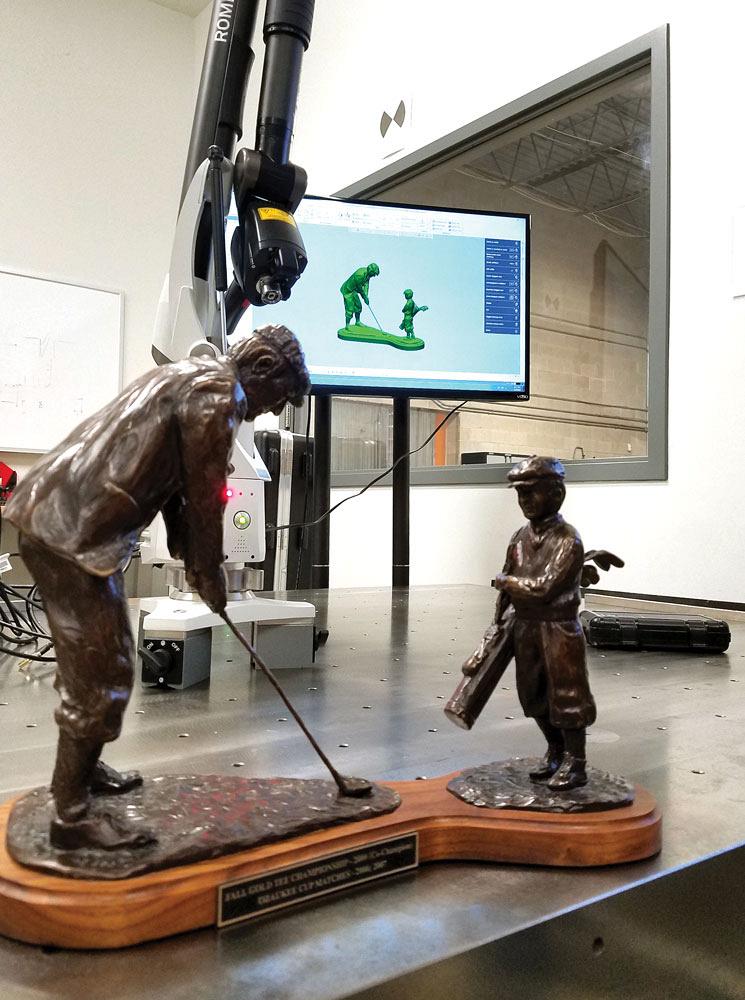
Portable arm-based laser scanning is becoming more popular in mainstream manufacturing and is a valuable tool for reverse engineering.
Know your tolerances. Meeting part tolerances is an everyday task in today’s machine shops, and the final deliverable should be perfect, right? Wrong.
Do you really need a sand casting, for example, to fall within 0.001 in.? Are you sure you want to see every imperfection in that part?
Reverse engineering is a path, a path with many twists and forks. This is one of those forks.
During the process, tolerances can be managed through use of the correct hardware and software in the hands of a skilled tradesman. Expectations, on the other hand, are still a bit of a slippery slope.
Modern scanning hardware has the ability to capture high surface detail, sometimes to the detriment or advantage of the process, depending on the previous factors mentioned, including anticipated changes.
If your intent is to create new tooling and develop clean surfaces for machining, then developing the part through a traditional CAD work flow makes the most sense. But, this calls for an allowance. An allowance of tolerance.
The intended flat surface may not be flat on the physical part once it is created. Through 3-D scanning and interpreting those surfaces back to a clean CAD model, you can correct that discrepancy, therefore influencing the deviation on the actual part back to its new digital CAD counterpart.
On the flip side, if you are developing something to perhaps grab or hold this part and you need high precision, then back to that prior fork in the road. You can now take a different approach to the modelling output. Similar to our engine example, you can create high-precision NURBS output to satisfy those exact surfaces and make certain the part is defined properly.
Now that you have the intent guidelines established, let’s examine your options based on those choices.
Advancements in technology over the last 20 years have been amazing.
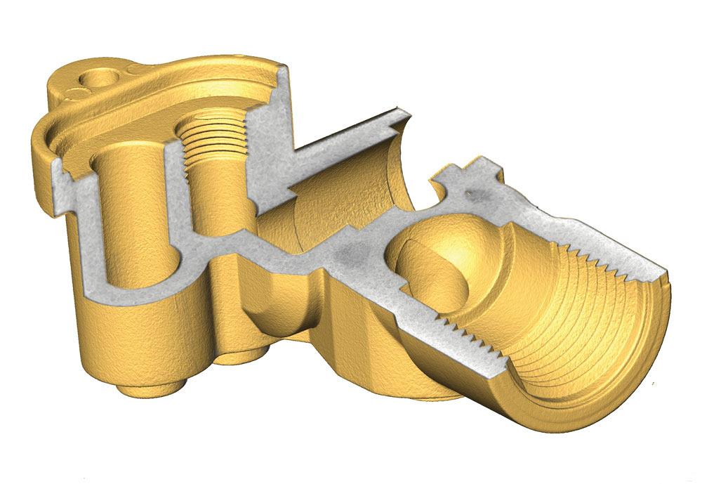
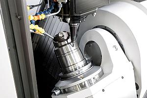
Internal features can be scanned and data collected to create a full part model.
Structured light is cleaner, portable arm-based laser scanning is much faster and more accurate, and time-of-flight and phase shift (long-range) scanners can scan farther distances with substantially higher precision. Metrology grade 3-D CT (X-ray) scanners also are becoming more powerful and financially feasible.
Why structured light? Because it produces clean data.
Clean data yields a cleaner result. Structured light typically comes from a two-camera stereo system. It uses a digital projector to project a fringe pattern onto the surface of the part, thus displacement of the fringe pattern along the part is correlated back into 3-D data. These sheets of lights are bounced off the part and provide a clean and highly accurate digital representation.
This clarity is regarded as a high standard in comparison to other methods. Its only real limitations are translucency/transparency and deep colours opposing the light spectrum of the projected light. Also, both cameras need to see the geometry that is being captured.
Why go portable? To maximize speed and flexibility.
One of the biggest improvements has been in the portable CMM industry. These systems produce wider laser lines, have higher hertz rates for data capture, and capture millions of points in seconds.
They also allow you to move them quickly from a controlled lab environment to a machine on the shop floor to resolve an issue.
Data from a portable unit is captured via laser, and its ability to adapt to different surface colours and finishes has become highly advanced in recent years. Chrome and deep blacks were always the nemesis, but those days are fading away. Quickly.
With tolerances getting close to matching those of structured light, portable arm-based laser scanning is taking a good hold on the market and becoming a dominant force and a valuable tool for reverse engineering. Current limitations are set only by the length of the portable arm, with multiple setups being required for part sizes beyond the arm’s reach.
Why is long-range scanning necessary? With the ability to scan geometry hundreds of meters away within a reasonable tolerance, long-range scanning is a perfect fit for the right application. These tools send out a laser beam with high precision and record the surface it bounces off back into digital 3-D data. That data can be combined with high-resolution imagery to provide 3-D visualization of the objects, areas, and even spaces being scanned.
Why CT scans? Visualizing internal data is typically lumped into the category of inspection work. But with 3-D X-ray machines becoming more powerful to see inside dense materials such as steel, extracting those internals can prove valuable.
Internal passages that were created with a complex network of sand cores in a foundry process can be seen to correctly validate clearances when re-creating a new part. CT also eliminates blindspots, allowing designers to model complex sculptural surfaces with precision and assumptions in filling in missing geometry from conventional scanning methods.
Garbage in, garbage out is the norm for any data collection and usage. With the variety of scanners mentioned previously comes a bit of responsibility. You should know your hardware, including its capabilities and limitations.
Once a 3-D point cloud is created, you will have millions of points that cleanly represent the part and you are ready for the next step. The common next step is converting the X/Y/Z 3-D data points into a polygon model. Simply put, the software connects the dots with a series of triangles to create a representative skin.
While various tools can accomplish this step, most hardware suppliers provide this direct output from their scanners, while others rely on third-party software to run the calculations.
Many software packages allow you to manipulate the data, including smoothing out imperfections and closing small or even absurdly large holes within a reasonable assumed precision. The ability to quickly edit out pesky clamps or fixtures holding the parts during scanning is amazing. This step sets the pace for the next round of modelling.
The conversion process comes next.
Polygon data, commonly referred to as an STL, needs to be converted to a useable format with the necessary parameters to get what you need out of it. Here, you come to the final fork in the road.
This conversion is also another part of this process that has dramatically improved in the last 10 years. The ability to get from physical part to 3-D data is much easier today. Gone are the days of scanning a part, bringing a low-resolution version into a CAD package, cutting cross sections, converting those to complex sketches, and then generating 3-D features off those sketches.
Today software packages can handle scanning data directly input into them from the scanning device, converting large data sets to high-resolution mesh data and generating native parametric CAD features, all in one package, thereby shaving days off the process and achieving a much better result.
Also, the ability to generate NURBS with extremely high precision has been a dramatic improvement. With complex algorithms able to solve data sets with complex surface geometry with a single button push, the process continues to get faster and faster, as well as more accurate. It’s the best of both worlds.
The last stage is validation.
Now that you have two pieces, the 3-D scan data and the intended CAD model, you can finish the process.
Before moving to manufacturing, or whatever downstream process required, you need to check the work.
Another feature that continues to improve is data validation.
Validation, used here, is the ability to show deviation of the scanned object compared to the CAD model being developed. This deviation typically is represented by a colour map, with each colour representing the 3-D distance each point varies from its CAD model counterpart.
Once this evaluation is complete and meets the expectations determined, the CAD model is ready to be delivered.
Greg Groth is division manager for Exact Metrology, www.exactmetrology.com.


Keep up to date with the latest news, events, and technology for all things metal from our pair of monthly magazines written specifically for Canadian manufacturers!
Start Your Free Subscription
Easily access valuable industry resources now with full access to the digital edition of Canadian Metalworking.

Easily access valuable industry resources now with full access to the digital edition of Canadian Fabricating & Welding.