


5x Applications Engineer
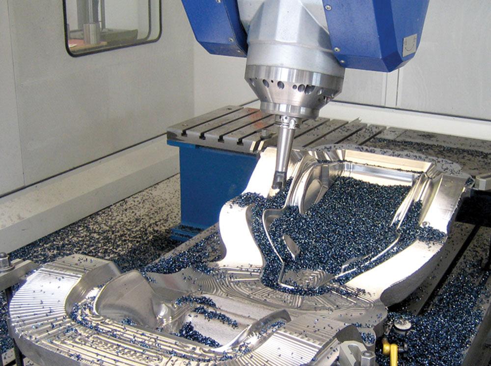
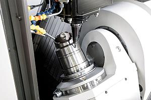
Complex, 5-axis parts benefit from vector programming.
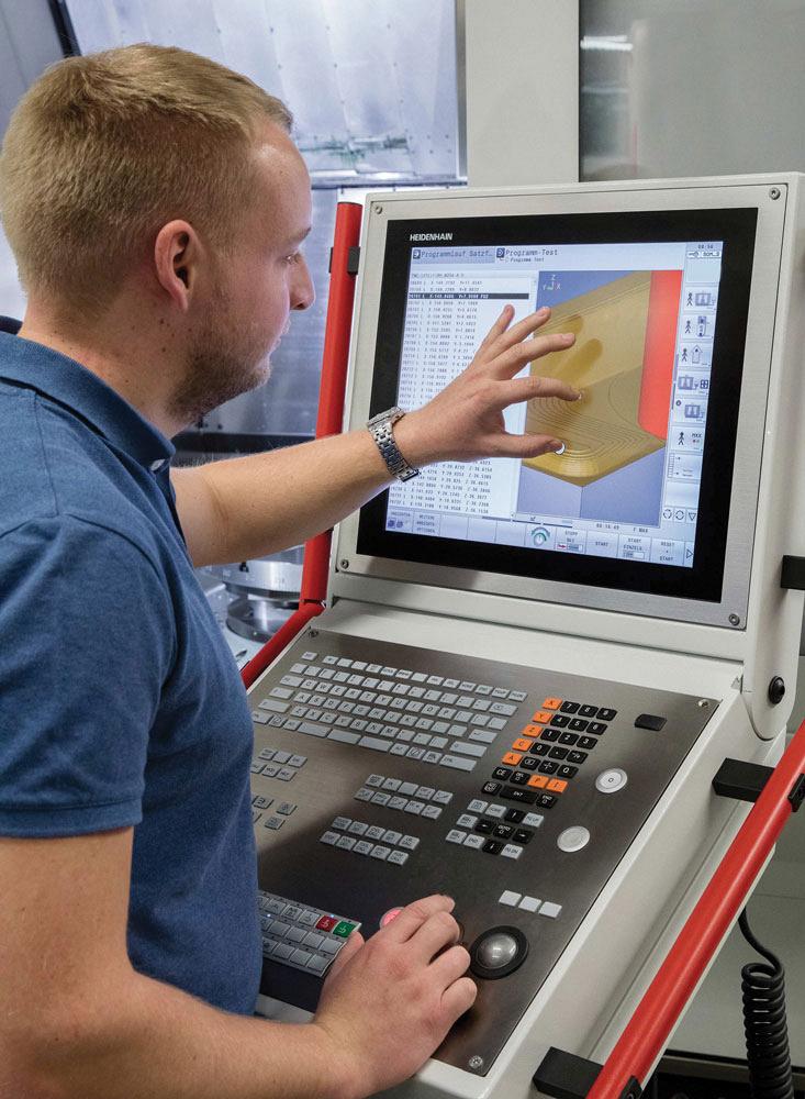
Many 5-axis control users access only a small portion of the power at their manufacturing fingertips.
The demand for quicker, more efficient machining of complex parts has been met with powerful 5-axis CNC functions, and the full features are impressive. As R&D continues in this area, expert tips are emerging.
For example, CNC users now have access to many forms of tool compensation not previously available. These 5-axis machining tools, of which many are unaware, enhance the ability for CAM programmers to better control their project.
One underutilized control technique that offers increased flexibility is vector programming.
To explain, a vector is a directed variable that specifies known direction and length. This variable is made up of components in the X, Y, and Z axes that describe where the beginning and end points of a vector lie.
But not all vector output is created equal. Sometimes code will be output in a CNC without the tool orientation (TXTYTZ) or without the surface normal (NXNYNZ). When pieces are missing, it limits the user’s ability to be as flexible as possible.
As an example, a normal full line of Heidenhain vector code might look like this: LN X Y Z NX NY NZ TX TY TZ M128.
More advanced controls, however, can enable more advanced code.
A standard vector output of all nine components on a TNC 640 Heidenhain control looks like this: LN X+36.0084 Y+6.177 Z-1.9209 NX-0.4658107 NY+0NZ+0.8848844 TX+0.0000000 TY+0.6558846 TZ+0.7548612 R0 M128.
Nine components make up one line of standard code and the M128, which tells the control that it is in full 5-axis compensation. To note, a normalized vector is a vector with a value of 1. The vector value is calculated from the root sum of the squares of its components: √(〖NX〗^2+〖NY〗^2+〖NZ〗^2 )=1.
Tool contact angle compensation is useful because every ball end mill has slight deviations in its radius.
The use of vector programming is particularly helpful because when a tool wears or a new tool is loaded into a machine, users do not need to repost the program or, worse, guess what the compensation should be. Compensation is made for reworked tools and, if the correct output is generated, can be used to create uniform oversize or undersize on the workpiece.
This means compensation can take place regardless of the tool’s contact angle. All these options are helpful to CAM programmers when it comes to 5-axis machining toolpaths, because they result in less maintenance on the machine and more accurate parts.
To employ these tips, users must have up-to-date CAM and a control that supports these techniques.
Tip 1: Compensate a reworked tool
Reduction in operator intervention to compensate for the resharpened tool on the workpiece surface helps minimize errors and increases precision.
If a operator is performing peripheral (swarf) milling, they shouldn’t have any problem using cutter compensation in standard code format (G-code/Heidenhain code), providing the control allows this and has the option or if using any form of vector output.
The reason someone can use any form of vector output is that compensation takes place as normal/orthogonal to the tool’s contact edge if not specified. In this case, normal to the tool axis (TXTYTZ) or having surface normal (NXNYNZ) will yield the correct result.
Programmers need to be aware, however, that if only tool axis vectors are available, they have to use radius compensation and needs to specify the direction of the cutter (cutter comp left or cutter comp right). This is because there will not be a normal vector to specify the proper direction.
If the operator is using all parts of the ball end mill (L/R), it is face milling. Think of a tool moving back and forth in 3x or 5x across a 3D dome. At the top of the dome, the operator is using more of the bottom of the ball, and at the sides of the dome or near the bottom, he uses more of the radius or edge of the ball. Many mould finish passes use this technique.
If the operator then wants to compensate for a resharpened tool perhaps running along and using both the L and R of the tool to cut, he will need a nine-place output vector code, similar to the previous example. This allows the user to compensate along the normal vector, because this vector describes a point on the surface normal to the tool. The user also can compensate along the tool axis because he knows the direction the tool axis is pointing on each line.
CNC users now have access to many forms of tool compensation not previously available. These 5-axis machining tools, of which many are unaware, enhance the ability for CAM programmers to better control their project.
Tip 2: Create a constant oversize or undersize
This is a big challenge in 5-axis machining. The ability to compensate one or both compensation values to achieve a constant oversize or undersize is needed. When vector code is not used, machines can run into problems in the form of gouges on the machined surface because the machine cannot make the compensation properly. This happens when the machine does not have enough data to make the proper moves.
Therefore, if the operator is running 5-axis code and wants to create a constant oversize or undersize, during face milling, the best, most efficient way to accomplish this is to use vector code. The programmer should be sure to specify the radius and length oversize.
For this we use delta length (DL) or delta radius (DR). Most likely, these specifications will be the same for a face milling technique. This ensures a constant removal or oversize of the machined surface without opportunity for the tool to take a wrong turn.
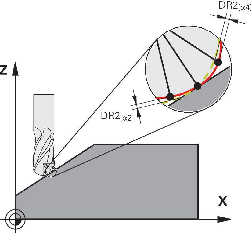
Tip 3: Compensate depending on tool’s contact angle
Tool contact angle compensation is a special option on Heidenhain controls. It is useful because every ball end mill has slight deviations in its radius. The radius on a 6-mm ball end mill is never uniformly exactly 3 mm around the centrepoint. Therefore, the control should measure part deviations in the radius using a laser tool measuring device that is inside the machine and can find as many as 30 points to define the radius.
This is a special cycle and the information it provides is tabulated in a table. A vector program with surface normal blocks (NX NY NZ) also is required. What happens is, for each angle of the tool, the control reads the appropriate angle and deviation on the ball to create a more accurate surface.
When an angle being used lies between two data points, interpolation takes place. This can help mouldmakers and manufacturers of aerospace components, as well as allow manufacturers of medical parts on finish toolpaths, to get closer to true surface integrity of the part.
Tip 4 (for Heidenhain users): Use IS Contour
The IS Contour function produces a program that is independent of the tool. The leading point is located where the tool touches the workpiece. This is helpful because the user can see the points whose coordinates describe the surface. Without this, the operator or programmer running the machine doesn’t really know where they are because a vector program is driving the tool.
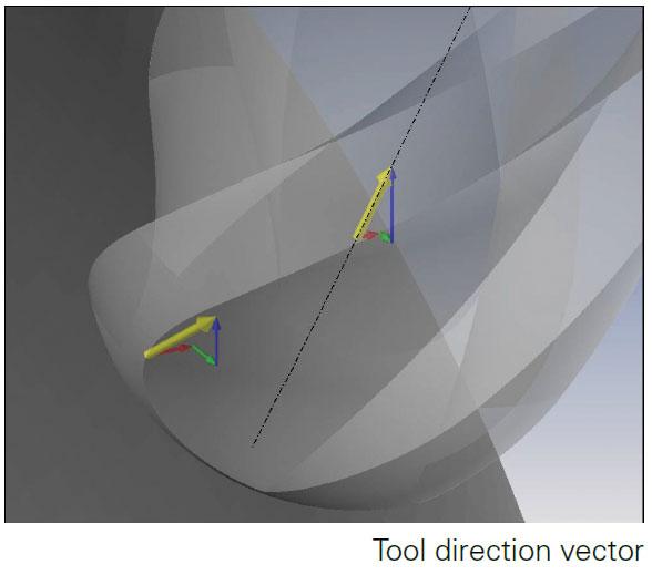
Many X, Y, Z components make up the surface normal and tool axis vectors.
Output in the CAM system must therefore be tool-neutral. This means that the surface points must be output with N vector or T vector in the CAM system.
In addition, the operator can read the contour points that describe the surface directly from the program without having to calculate back to the surface coordinates, for example, via the tool corner radius R2. Another advantage is that the operator can use such a point directly from the NC program and then check it with a measuring cycle to see if it is within a certain tolerance.
In the actual value display, the operator will always see the tool leading point (for example, the ball centre of the ball milling cutter).
If an operator is programming finish passes in vector format with a 5-axis control and using a reworked or resharpened tool, there is no need to recalculate or post new code to the machine; proper vector output takes care of this. This results in improved accuracy and time savings.
Joe Pizzoferrato is a 5x applications engineer for Heidenhain, 333 E. State Parkway, Schaumburg, Ill. 60173, 847-440-3992, www.heideinhain.us.


Keep up to date with the latest news, events, and technology for all things metal from our pair of monthly magazines written specifically for Canadian manufacturers!
Start Your Free Subscription
Easily access valuable industry resources now with full access to the digital edition of Canadian Metalworking.

Easily access valuable industry resources now with full access to the digital edition of Canadian Fabricating & Welding.