


Head of Business Development
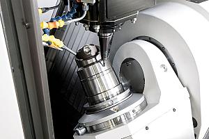
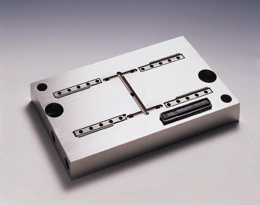
Multiple factors involved with the EDM process contribute to maintaining corners, sharp angles and radii. Photo courtesy of GF Machining Solutions.
EDM is a noncontact metal removal process that can cut complex shapes with accuracy up to +/-1 µm and generate surface finishes finer than 0.1 µm RA in hardened and difficult-to-machine conductive materials, without creating distortion or stress. Consequently, wire and die sinking EDM offer, in some cases, the only practical ways to accomplish precision machining operations in critical applications for the medical, aerospace, electronics, and other industries.
Maintaining such high levels of accuracy–especially when it comes to corners, sharp angles, and tight radii–requires close control of the multiple factors involved in the EDM process. In wire EDM, for instance, a key issue is achieving consistent production of corner radii. Wire EDM is capable of producing corner radii barely larger than the radius of the cutting wire itself. However, in parts such as stamping dies, a corner radius that is too small can become a geometric stress point from which cracks can originate.
Choose the Right Wire
CAM software for EDM provides a way to relieve excessively tight corner radii. In cases where a machined radius would be too tight, the software can be set to direct the wire to move in small loops--similar to a trochoidal milling path--to relieve the radius. For example, when an operator iscutting with a 0.005-in.-diameter wire, the looping toolpath might add 0.002 in. and produce a 0.007-in. corner radius.
Generating very sharp internal angles also can pose a challenge. In some situations, the wire diameter may be too large to erode the full depth of an acute corner, much like attempting to machine an intricate feature with an end mill that is too big. The reason is that the EDM machine control maintains a set spark gap, or offset, between the wire and the workpiece to achieve a desired material removal rate at a certain power level.
A wire diameter that is too big for the application will reduce the offset to the degree that machining stops before completing the angle. Use of a smaller-diameter wire—say, 0.002 in., 0.001 in., or 0.0
008 in.--enables machining of acute angles. But smaller wires cut more slowly and are more prone to breakage, making them impractical for more general use.
A productive alternative is a machine with an automatic wire changer that enables quick exchanges between two spools of wire that can be completely different in type and diameter. So, an EDM could perform roughing and cut large features with large-diameter wire then automatically change to a spool with small-diameter wire to cut the very tight part details.
An operator may rough a corner at high cutting speeds and return for a cleanup pass that quickly removes a small amount of material.
Control Cut Parameters
When a wire EDM operation is initialized, achieving accurate results in sharp corners or tight radii depends on a multitude of factors. These include wire type, diameter, tension, and feed conditions; workpiece material and thickness; dielectric type, flow, and temperature; and spark power and duration.
Traditionally, fine-tuning an EDM process required cutting a test part and then removing it from the machine for measurement on a CMM. After remounting the part on the machine, the operator consulted the CMM data to note deviations from the desired part dimension and made changes in the machining parameters with the hope of achieving an acceptable part. A newer approach uses a closed-loop vision system to measure the part and make in-process corrections.
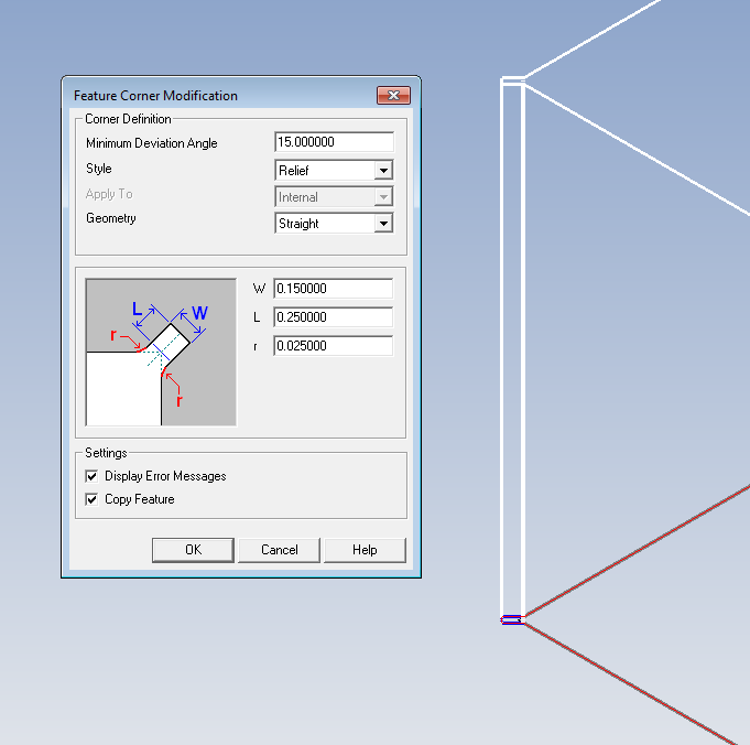
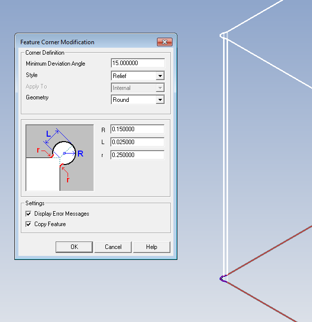
While the part remains in the machine, the system’s camera scans the part contours and compares them to the part’s DXF CAD file. If the part is out of specification, the system employs what is called a contour modifier that directs the machine control to correct the EDM path to produce a part within 0.0001 in. (2.5 µm) of the required dimensions. A vision system can also facilitate quick location of a part before machining begins, saving the time and wire invested in the traditional part location method that uses the wire itself to locate the part on the machine.
Control of the wire’s path when producing inside and outside corner radii is another important element of EDM process accuracy. When the EDM wire rounds a corner, it can act somewhat like an 18-wheel semi making a turn--where the front wheels track perfectly but the rear of the trailer swings wide. While EDM wire guides hold the wire’s position above and below a workpiece, the wire’s middle section between the guides may swing wide during the cutting operation.
Advanced EDM machines and software provide methods of anticipating and eliminating the wire’s swing, thus reducing the risk of exaggerated corner paths. Twenty years ago, controlling corner machining required manually updating the CAM program to reduce power as the wire entered a corner. Reduced power/spark intensity then permits the application of greater wire tension to eliminate swingout and increase accuracy without causing wire breakage.
Today’s EDM software packages look ahead and change parameters in anticipation of upcoming part features such as corners and radii. On some machines, for example, software automatically reduces the intensity of the spark to prevent overcutting on curves. However, spark intensity not only influences metal removal rates, it also dictates required offset amounts. When power settings lower, the offsets must change accordingly. In many cases, however, decreasing power and also the flushing volume will increase the heat of the operation and keep material removal rates steady, eliminating the need to adjust the offset. For this reason the most common form of corner control involves pairing reduced power with adaptive flushing.
On a machine with a vision-based in-process measuring system, corner control can consist of reversing the wire path after traversing a corner and backtracking to complete the desired amount of metal removal. The reverse pass will be faster than the initial pass because a minimal amount of material is being removed.
Wear partitioning, a sinker EDM generator function, manages electrode wear when machining multicavities.
Because the lower power employed in corner control slows the overall machining process, shops often opt to turn automatic corner control off when the slower cutting speeds are impractical. For example, implementing corner control when rough machining the multiple teeth of a gear generally consumes an unacceptable amount of time. An operator might choose to rough the gear shapes at higher cutting speeds and then return for cleanup passes that run quickly.
Another factor affecting the accuracy of EDM operations in terms of corners, radii, and angles is the thermal condition of the cutting environment and machine. Wire guides set up first thing in the morning when a shop is 68 degrees F will perform much differently in the afternoon when that same shop is 78 degrees F and the machine is thoroughly warmed up. A typical negative effect of inconsistent thermal conditions is cone-shaped radii. As a solution, some machines are thermally stabilized. The control system minimizes thermal variations with the use of temperature-stable dielectric to cool the casting of the machine in conjunction with X, Y, U, V, and Z glass scales.
Die Sink Accurate Features
Die sinking EDM presents challenges different from those of wire EDM in regard to maintaining machining accuracy of corners, angles, and radii. While the wire EDM process continually presents fresh wire–unworn electrode–to the workpiece and cutting zone, a die sinking EDM electrode begins to wear as soon as erosion starts and continues to do so throughout the process. As the electrode wears, it gradually loses its ability to hold fine detail, so minimizing electrode wear is critical to improving accuracy. Plus, longer electrode life helps reduce the costs associated with electrode material as well as the time involved with machining it to the required form.
The wear rate of a sinker EDM electrode depends to a large degree on the material from which it is made. Conventional graphite conducts electricity well but wears quickly, so for creating sharp details, shops often apply electrodes formed from harder materials such as copper or copper/tungsten. These harder materials hold detail better than graphite, but do not conduct electricity as efficiently, so the result is slower machining.
Because lower cutting speeds extend electrode life but reduce productivity, EDM machine builders develop machine technologies and application strategies that balance cutting speeds with long electrode life and the ability to maintain sharp detail. And usually EDMing small, tight details requires multiple electrodes.
The normal progression employs one or more roughing electrodes followed by finishing passes with smaller electrodes. One application strategy to minimize the number of electrodes required to machine a part involves electrode staggering, or partitioning. Different electrodes are applied across multiple cavities in a sequence designed to maximize electrode life. Other process parameters, including the selection and duration of electrode orbit paths, are varied as well. While electrode wear decreases, overall burn time remains the same.
Reduce Time and Cost With Technology
To increase EDM accuracy and control costs, shops are demanding smaller wire EDM offsets and smaller undersize dimensions in die sinking operations. The goal is reduced process time and expense. Shrinking offsets and undersize dimensions require precise control of the spark gap, causing EDM machine manufacturers to pursue advancements in spark generator and machine control technologies. One such advancement is 100 per cent-digital generators.
Complete digital generator technology has enabled the development of special EDM functions which are engineered to minimize electrode wear while optimizing cutting speeds. On certain die sinking EDM equipment, the technology manages the electrical current between the fronts and sides of electrodes and controls its delivery to minimize lateral sparking that disrupts effective machining of areas such as the sides of mould cavities. The system allows the electrode to have maximum power in the front of the cavity without destroying or creating oversize gaps on the cavity side walls.
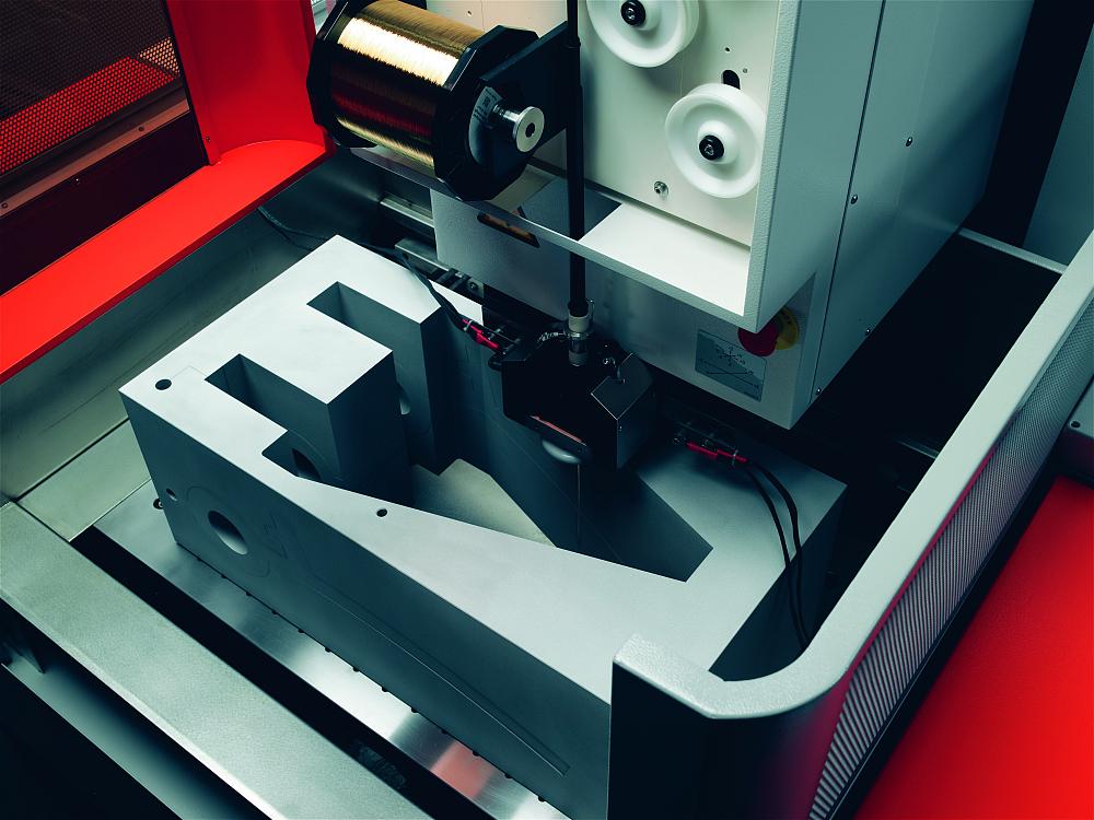
A wire EDM is capable of producing corner radii only slightly larger than the cutting wire itself.
Another technology aimed at extension of electrode life is a zero-electrode-wear feature. In both copper and graphite, the technology captures the debris/chips of the EDM erosion process and uses them as a protective and “healing” layer on the electrode, maintaining its edges and ability to produce fine details. The feature can reduce electrode use by two-thirds and in some cases permits the use of coarse graphite grades where finer grades were previously required. The technology also manages pulse efficiency to minimize wear and conserve electrode material.
Whether the goal is cutting corners, sharp angles, or tight radii, EDM OEMs continue to develop new technologies and hone the capabilities of their machines to efficiently and accurately generate tight intricate part features. As they do, the production benefits of the EDM process spread to a wider range of high-precision machining applications across an increasing number of industries.
Eric Ostini is product manager at GF Machining Solutions, 847-913-5300, www.gfms.com.


Keep up to date with the latest news, events, and technology for all things metal from our pair of monthly magazines written specifically for Canadian manufacturers!
Start Your Free Subscription
Easily access valuable industry resources now with full access to the digital edition of Canadian Metalworking.

Easily access valuable industry resources now with full access to the digital edition of Canadian Fabricating & Welding.