


Associate Editor

Inner diameter part clamping provides greater accessibility to part features, requiring no gripping mechanism on the exterior of the part. Photo courtesy of Hainbuch.
Traditional clamping options for turning operations tend to focus on gripping the outer diameter (OD). Yet experts agree that inner diameter (ID) part clamping is becoming more commonplace, especially as more shops purchase new lathe equipment having a twin-spindle configuration.
“The current trend we see is for shops to be investing in machines with two spindles as opposed to a main spindle and a tailstock,” said Tom Sheridan, president, Royal Products, Hauppauge, N.Y. “On the second spindle, ID workholding is really starting to catch on and is becoming more valuable.”
With twin-spindle machines, the component is in a raw state on the main spindle. In this stage, it often makes sense to machine the inside components and ID features. Once this operation is complete, the part is transferred to the subspindle so that now you can grip internally with a clamping device, like a mandrel, on the features that you just machined to allow full access to the OD.
“It really makes sense when you think about part processing,” said Dean Winkel, sales representative for Canada, Hainbuch America, Germantown, Wis. “Shops don’t want to handle the parts [more than necessary]. They want to transfer from one spindle to the next and, if possible, get the part off the machine complete. And ID part clamping on the subspindle helps make that possible.”Some shops stick to OD clamping because that’s the way it has always been done, and not all components have a bore, which is essential for ID gripping.
“In a perfect world, every part would have a bore that you could clamp it from,” said Winkel. “But we all know they don’t. So sometimes you just don’t have a choice; you do it another way.”
According to the experts, one of the most significant benefits of ID part clamping is the accessibility. ID clamping requires no gripping mechanisms on the outside profile of the part, which means that it does not interfere with tooling. And all external diameter features can be turned in a single operation, optimizing concentricity, which is a desirable characteristic that experts are seeing more of as tolerances get tighter.
When using a subspindle machine, operators also need to consider how gripping configuration will affect surface conditions.
“Instead of machining a portion of the part in one operation and a portion of it with a second operation, you get full access to the whole length of the component,” said Sheridan. “With the twin-spindle configuration, it’s important to consider that when a part is processed on the main spindle, then transferred to the subspindle, if you grip on the OD surface that has already been machined, there is the potential to damage or mark the surface.”
Sheridan also points out that on many parts, the engagement length of an ID bore can be greater than what is available for OD gripping because of the part configuration, resulting in increased rigidity and torque transmission.
It has only been in the last few years that ID part clamping has become a serious workholding option. The experts agree that although the mandrels and ID clamping options have been available, they were often overlooked for more traditional methods because of the many misconceptions floating around.

With twin-spindle machines, ID clamping can be used on the subspindle to grip internal features that were machined using the main spindle, allowing full access to the outer diameter. Photo courtesy of Royal Products.
“Years ago people didn’t really know ID clamping was an option,” said Winkel. “Mandrels at the time tended to be fragile and custom, which meant there was a long lead time in acquiring them, and they were costly. At the time there wasn’t a product that was standard, off-the-shelf, or modular, for that matter. So people assume that’s still the case when it really isn’t.”
Today many different options are available on the market. Winkel explained that it’s not a one-size-fits-all device, but with quick-change options and adaptable components, shops can purchase one mandrel that can be changed over to other parts quickly and with minimal investment.
“There’s a misunderstanding in the industry where shops believe that the [clamping] bushing must match the length of the bore or length of the part,” said Winkel. “That’s simply not the case. We’ve worked many applications where we’ve clamped on a very short length and it’s worked well. Of course, we understand what the process is, what the shop is trying to achieve.”
It’s important to be realistic when exploring ID clamping. Just because a part has a bore doesn’t mean that a mandrel is the best choice. Part configuration plays a key role in whether the part can be gripped on the ID. Sheridan explained that, for example, if the bore measures Ø25 mm with a depth of 12 mm, but the OD of the part is 200 mm, clamping on the ID wouldn’t necessarily transmit enough gripping torque to effectively machine the part.
Another common misconception is that mandrels are fragile and not a robust way to clamp a part. According to Winkel, people believe this because mandrels traditionally consisted of a slotted collet or a slotted bushing; manufacturers created the device by cutting slots into it and making it expand. However, there were significant limitations in the expansion capability.
“If this style of collet was expanded too many times without a part, the stress accumulated in the collet, which could lead to failure,” said Winkel. “So many thought, ‘If I hit the footswitch that actuates the cylinder to the machine, is there a chance that I’ll break the collet?’ That was a common thought that we try to dispel with the newer options available.”
Winkel noted that many newer mandrels use a vulcanized rubber bushing setup in which steel segments are vulcanized together. This design ensures that even if you actuate the mandrel multiple times without a part, it will not break.
The trend in twin-spindle lathes has certainly opened users’ eyes to the significance and applicability of ID part clamping. However, clamping on the ID generally has been used in gear production, where it really made sense. The experts noted that now more milling applications are also being clamped using this method.
“Choosing the best clamping option depends on the customer’s application,” said Josh Herschbach, senior engineer, Carr Lane Manufacturing, St. Louis, Mo. “If they need to have access to the entire profile of the part, depending on the part size, where it’s being machined, and how much force is being exerted based on the machining method, it would be a great solution for many milling customers.”
The advantages of using ID clamping on a mill and a lathe are similar. Herschbach noted that one of the benefits he sees with ID workholding options for milling is the ability to fixture multiple parts.

All external diameter features can be turned in a single operation, optimizing concentricity, which is necessary to meet tight tolerances. Photo courtesy of Hainbuch.
“It can easily be used for one-offs as long as it has an internal bore,” Herschbach said. “But it also has to be bolted to a fixture plate, where it has quick-change abilities, which is great for large-scale production. Self-centring clamps allow for close mounting for multipart machining on both vertical and horizontal machining centres.”
Gear manufacturing is not the only application that is suited for ID clamping. Five-axis milling machines or machines with a fourth axis also have helped shops adopt this method. Instead of jaws, dovetails, or any other clamping method, a mandrel would give you almost perfect access to five sides of the part that would not be possible with other workholding devices.
“At tradeshows, one of the most common parts we see demonstrated on 5-axis machines is the impeller,” explained Winkel. “It’s very impressive to watch [it] being machined. But they’re often fixtured using three-jaw chucks. When you think about how the part connects to the engine using a shaft, it only makes sense to clamp it the same way that it would be fastened in its end product. It makes a lot more sense to clamp it with a mandrel. This process hasn’t yet worked its way through the industry. We are hoping to change that.”
Associate Editor Lindsay Luminoso can be reached at lluminoso@canadianmetalworking.com.
Carr Lane Manufacturing Co., www.carrlane.com
Hainbuch America, www.hainbuchamerica.com
Royal Products, www.royalproducts.com
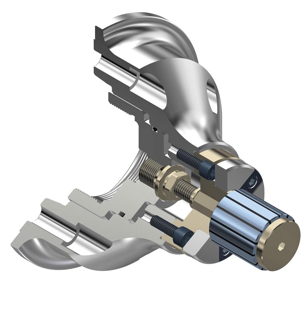
Many features and mechanisms in today’s mandrels ensure they provide rigid and accurate ID clamping. Photo courtesy of Royal Products.


Keep up to date with the latest news, events, and technology for all things metal from our pair of monthly magazines written specifically for Canadian manufacturers!
Start Your Free Subscription
Easily access valuable industry resources now with full access to the digital edition of Canadian Metalworking.

Easily access valuable industry resources now with full access to the digital edition of Canadian Fabricating & Welding.