Turning Manager
- FMA
- The Fabricator
- FABTECH
- Canadian Metalworking
Interrupted Turning
Innovations in turning tooling combat the challenges of interrupted cutting
- By Derrick Evers
- September 1, 2009
- Article
- Metalworking
Turning is a game of fundamentals more so than other machining operations such as milling, drilling, or grooving.
There is really nothing fancy about turning. It is about selecting the optimal insert for the application and applying it properly in an efficient manner. If the insert has an advanced coating technology specific to the application and it is applied effectively, maximum productivity is ensured. This is turning fundamentals 101.
Interrupted Cutting
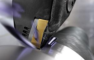
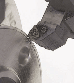
An interrupted, or intermittent, cut in turning occurs when the tool is not in constant contact with the workpiece. This fluctuation in both thermal and mechanical load can negatively affect cutting edge integrity, productivity, and process security.
Indexable carbide inserts work well under constant loads. However, the main property of carbide is that it is harder than the material being machined. Therefore, carbide has good wear resistance properties, but it lacks toughness. Without proper process control, difficult machining conditions such as interrupted cuts can cause chipped cutting edges, thermal cracking, or even breakage.
With interrupted cuts, if the cutting edge breaks down prematurely or inconsistently, process security becomes an issue, and part quality will be affected.
Optimal Insert Selection
One of the best ways to increase productivity and process security is to ensure an optimal insert is selected for the application.
Before insert geometry and grades are considered for interrupted cuts, take a look at insert shape, rake angle, and approach angle. The strongest insert shape should be used.
For example, a round insert is the strongest shape, followed by square. The larger the cutting edge angle the better. With rake angle, a negative rake is stronger than a positive rake, and a smaller approach angle not only thins the chip, but spreads out the forces from an interrupted cut over a larger portion of the cutting edge.
A good process for selecting the optimal insert takes into account the chipbreaker and grade, feed, depth of cut, material, machining conditions, and optimal cutting speed.
Machining conditions include the machine, clamping system, and workpiece. Factors considered are stability of the machine, clamping, and workpiece and workpiece conditions such as part skin or crust, changing depth of cut, and level of interruption.
Insert Geometry
To be able to handle interrupted cuts or difficult machining conditions, the cutting edge must be strong and able to tolerate fluctuations in mechanical load. The geometry of the cutting edge varies with different chipbreaker designs. In essence, each chipbreaker is designed to handle a feed rate and a depth of cut within a specified range.
The cutting edge geometry is therefore designed for the cutting force relative to this feed and depth of cut. So the first step is to select a chipbreaker relative to depth of cut and feed, or select a chipbreaker relative to depth of cut and reduce the feed rate to the lower end of the specified range. This technique can be used initially to establish a stable and secure process, and then feed can be maximized later.
Additionally, several chipbreakers may be suitable for the specified depth of cut, but choosing the strongest one will limit the effects of the interruption.
To determine which insert has the strongest edge, look at two inserts and compare them visually. A stronger edge is typically characterized by a land (flat or chamfer), or hone (rounded edge). Naturally, the larger the land, hone, or chamfer, the stronger the edge.
Simple and Innovative Grades
Typical grades for interrupted cuts must have a high toughness. Toughness is usually measured by transverse rupture strength.
Using the optimal insert for the application is key, but so is having a state-of-the-art product.
Most turning innovations have been related to developments in coating technology. Insert substrates and geometries have not undergone the progress that coatings have in the past 15 years. Since ISO standard shapes and sizes apply to turning inserts, only so much can be done with chipbreaker geometry, which is basically a series of angles and curves.
Substrates have progressed, but essentially the content of carbide has not changed.
However, more control has been placed on the process used to manufacture insert substrates. The ability to control the process is due to advancements in computer technology that controls and measures the substrate manufacturing process. This has improved the quality and extended the range of applications for carbide inserts.
Computers have had even a greater effect on coating technology than on substrates. The ability to control the temperature and gas flow to a coating furnace through computer technology has led to many advances in insert coatings.
As with the insert substrate, coating toughness also improves an insert’s ability to machine interrupted and difficult cuts.
Equally important is the bonding of the coating to the substrate. If the coating process is not controlled, carbon can be depleted from the substrate, and not only is a poor bond formed, but the integrity of the substrate is compromised. Modern computerized coating furnaces place more control on the process and minimize these detrimental effects.
For coating carbide inserts two main processes are used: PVD (physical vapor deposition) and CVD (chemical vapor deposition).
PVD coatings typically are tougher than CVD coatings, which is why PVD grades are normally used for milling, which can be defined as an interrupted cut.
PVD coating has enhanced toughness for two reasons. First, it is performed at approximately half the temperature of CVD coating. Therefore, less cracking occurs in a PVD coating as it cools after being applied because at the lower temperature the coating and the insert substrate cool at a similar rate.
With CVD coatings, high impact forces from interrupted cutting attack the cracks in the coating, causing a CVD insert to wear more quickly.
Additionally, the smoothness and the reduced cracking in PVD coatings allow the insert to better handle the temperature fluctuations of an interrupted cut. These fluctuations occur because the insert is exposed to heat and then cools rapidly after the cut.
The second reason a PVD coating may be better suited for interrupted cuts is that the coating process places a higher inherent stress on the insert. This allows the insert to withstand high cutting forces that are encountered in interrupted cutting.
The application range of Walter’s PVD Tiger-tec is also increased because of unique features that increase wear resistance by providing a thermal barrier that shields the insert from temperature fluctuations produced by the interrupted cut.
For more information, visit www.walter-tools.com.
Is Dry Machining Better?
Machining dry prevents insert temperature fluctuations, but there is no hard-and-fast rule as to whether interrupted turning is better performed dry because so many factors influence the manufacturing process.
Typically, the main function of coolant is to provide the lubrication that reduces friction, cools the tool, and aids in chip evacuation.
Once again comparing interrupted turning to milling, some materials can be machined dry easier than others. Cast iron is a short chipping material, so it is the easiest to machine dry. Steel is the next easiest to machine dry. However, stainless steels, difficult-to-machine materials, and aluminum form chips that don’t break as easily and can stick to the tool. Coolant may prevent this problem.
About the Author
subscribe now

Keep up to date with the latest news, events, and technology for all things metal from our pair of monthly magazines written specifically for Canadian manufacturers!
Start Your Free Subscription- Industry Events
MME Winnipeg
- April 30, 2024
- Winnipeg, ON Canada
CTMA Economic Uncertainty: Helping You Navigate Windsor Seminar
- April 30, 2024
- Windsor, ON Canada
CTMA Economic Uncertainty: Helping You Navigate Kitchener Seminar
- May 2, 2024
- Kitchener, ON Canada
Automate 2024
- May 6 - 9, 2024
- Chicago, IL
ANCA Open House
- May 7 - 8, 2024
- Wixom, MI


