


Product manager, press brake tooling
Many consider press brake tooling a minor accessory in metal forming when in fact the opposite is true. In the first part of this two-part series, we discussed the minimum requirements for tooling and clamping, as well as some details of punch selection. This month we continue that discussion
Don't miss the first part of this two-part series on the requirements for tooling and clamping as well as some details of punch selection
Punch Selection Rules
For L shapes the rules are … there are no rules. Almost any punch shape will work. So when selecting punches for a group of parts, you always should consider these L-shaped parts last, considering just about any punch shape can handle them.
When forming these L shapes, use a punch that also can form other parts, rather than adding unnecessary tools to the library. Remember, when specifying tooling, less is always best—not just to minimize tooling cost, but also to reduce setup time by reducing the number of tool shapes needed on the shop floor (see Figure 1).
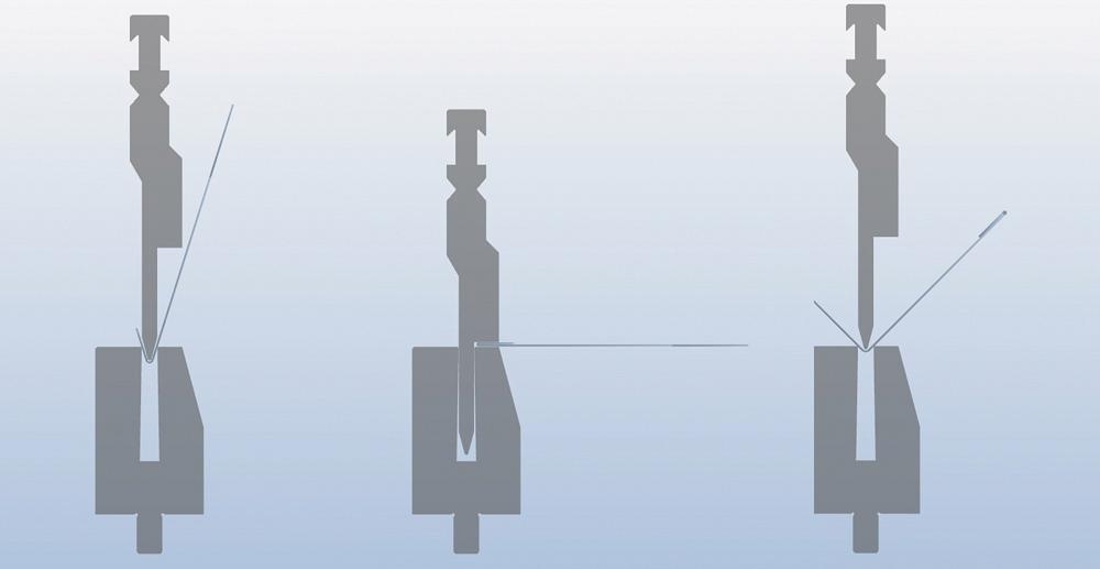
Other shapes do require specific rules for punch selection. For instance, when forming J shapes, the rules are (see Figure 2):
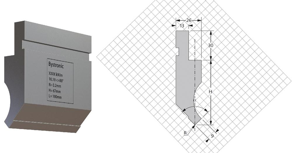
As you can see, the punch selection rules deal mostly with workpiece interference, and this is where bending simulation software can play an important role. If you don’t have access to bend simulation software, you can use your tooling supplier’s drawings with grid backgrounds to check for punch-part interference manually (see Figure 3).
Offset Rules
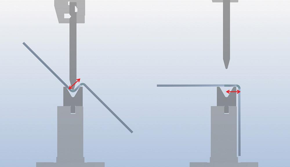
If you’re using a conventional toolset, you’ll need to use two ram cycles to form offsets or Z shapes. For these shapes, the rules are (see Figure 4):
Rules for Bending Across Cutouts and Mitres
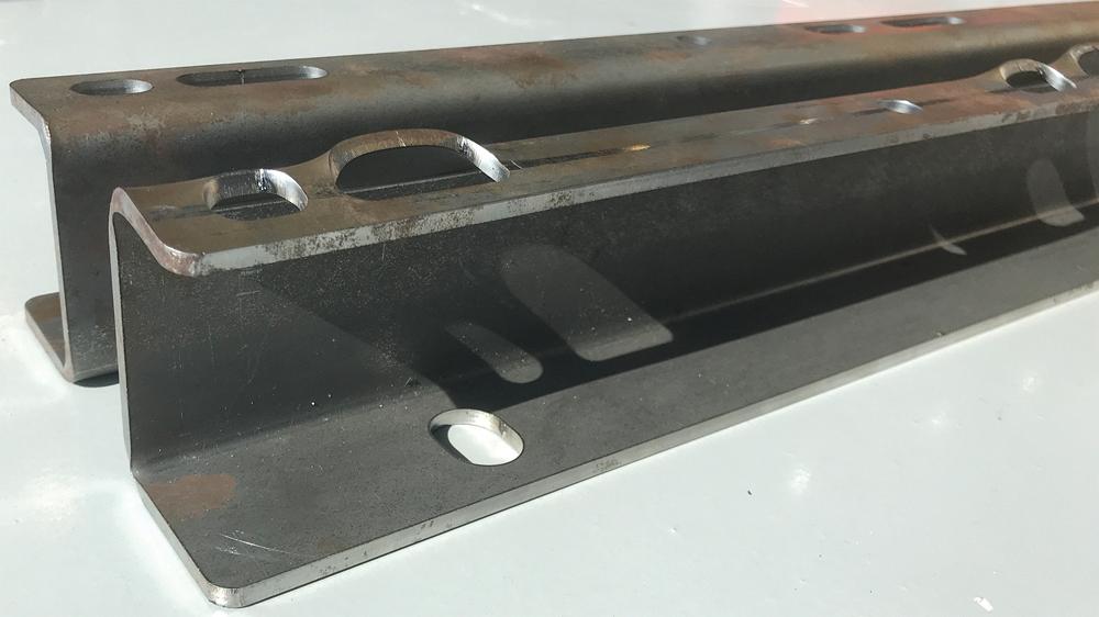
Any unsupported material inside the V die is subject to deformation; in holes and other cutouts, this deformation manifests itself as blowouts (see Figure 5). When the holes near the bend lines are small, the associated blowout will be small too. Also, most applications will accept some distortion, so there is no definitive rule on the best V-die width to choose when a cutout is on or near a bend line.
When the flanges, cutouts, and mitres are clearly too close to the bend line for the metal thickness, you can specify rocker-type dies. The rockers rotate and support the material throughout the entire bending process and, thus, eliminate the blowout.
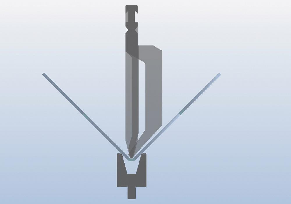
Figure 1 - For many parts, the punch shape does not cause any bending restrictions.
Figure 5 shows identical parts with cutouts close to the bend lines; the foreground one—with the telltale blowout—was formed using a conventional V die; the background one was formed with a rocker-type die. Also note that the two ovals on the left have the same width (front to back) and are the same distance from the bend line; only their lengths are different. You can clearly see more blowout on the longer oval.
Punch Height for a Given Box Depth
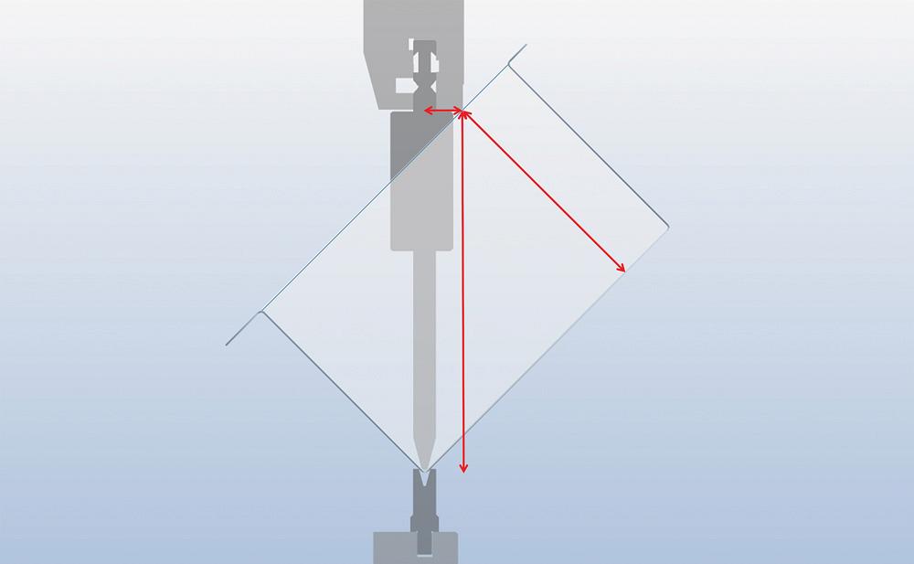
Punch height becomes critical when forming three- and four-sided boxes. In some cases, short punches can form three-sided boxes if one formed side can hang off the side of the press brake during the final (third) bend. If you’re forming four-sided boxes, you need to choose a punch tall enough to span the box height diagonally (see Figure 6):
Minimum punch height for box bending = (Box depth/0.7) + (Ram thickness/2)
If there are no top (return) flanges, or the top flanges protrude outward, you won’t need much clearance between the top punch and lower die to remove the part after bending. But if you do have return flanges (top flanges that protrude inward) on all four sides, you need enough clearance to twist and remove the box after bending.
Combination Bend and Hem
Bend-hem tools can form parts with hemmed edges in a single setup, as shown in Figure 7. Just know that if you need to hem thicknesses greater than 0.125 in., you might need custom tools to accommodate the excessive forces required.
V-die opening selection rules here are basically the same as for standard bending tools. The 30-degree prebends for the hems do require somewhat longer minimum flanges—at 115 per cent of the selected V-die opening—because of the acute angles. For instance, if you’re forming material over a 0.375-in. V die, you’d need the flange to be at least 0.431 in. (0.375 × 1.15).
Scratch-free Parts
Almost all typical V-die bending tools leave some marks on the part, simply because the metal is being drawn into the die while bending. In most cases the marking is minimal and acceptable, and increasing the shoulder radius can reduce the markings.
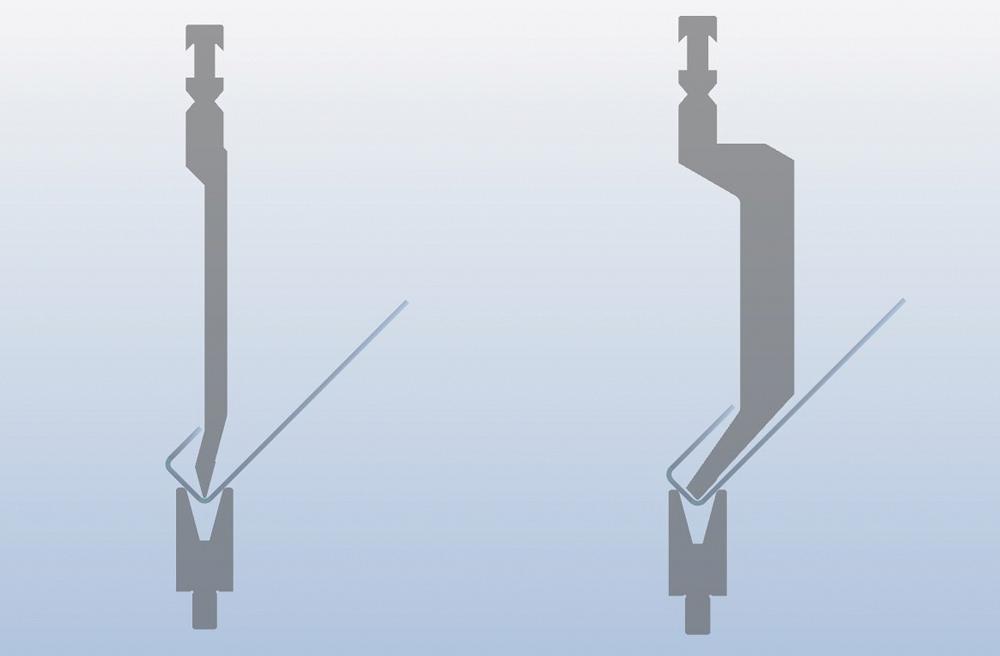
Figure 2 - Certain J shapes have specific punch selection rules. When the small up-leg is equal to the bottom leg, you need an acute offset punch (shown on the left). If the up-leg is longer than the bottom leg, you need a gooseneck punch (shown on the right).
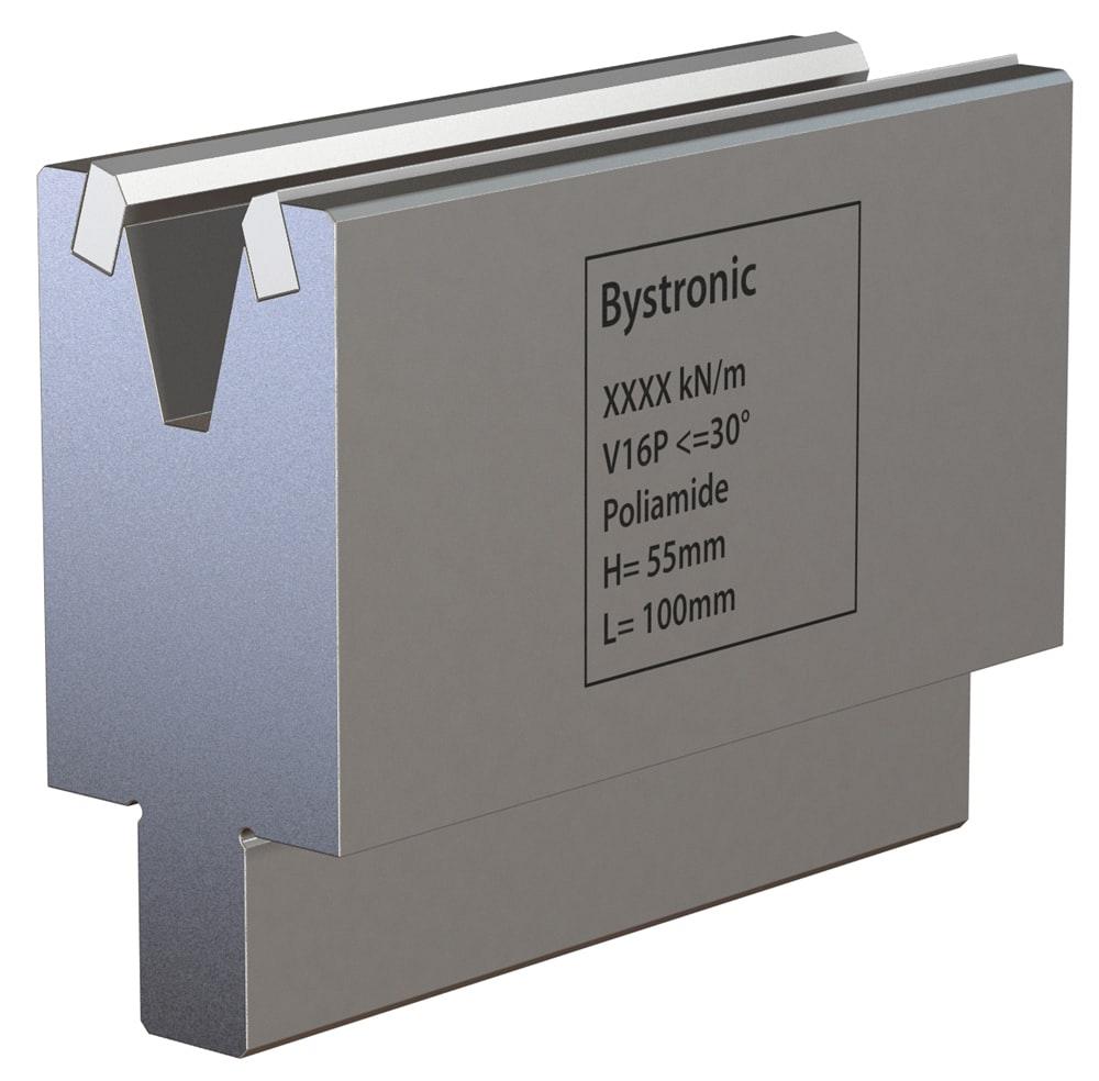
For applications where even minimal marking is not acceptable, like when bending prepainted or polished materials, you can use nylon inserts to eliminate scratching (see Figure 8). Scratch-free bending is especially important for fabricating critical aircraft/aerospace parts, because it’s hard for inspectors to visually inspect a piece and tell the difference between a scratch and a crack.
Simplicity Is a Virtue
Today’s precision tooling and press brakes can reach unprecedented levels of accuracy. And with the right tools and consistent material, a press brake operation can bend a flange to a specific angle with a specific inside bend radius. But again, air bending forms the inside bend radius to a percentage of the die opening—and having the right tools matters. Specifying a multitude of different, tightly toleranced radii will increase tooling costs. And the more tools you need, the more changeovers you’ll have, which increases costs even more.
That said, sheet metal part designers can make tooling selection and the overall bending operation much easier if they follow a few basic rules when designing parts:
Exceptions to these rules abound, and each comes with complications. You can use a narrower V-die opening to bend a tighter radius or a shorter flange—but bend too sharp a radius and you risk creasing the bend line and exceeding the tonnage rating for the tooling and press brake. You can bend a narrower offset, but again, that requires a special tool and significant forming tonnage.
If a part doesn’t need a short flange, a narrow offset, or a tight radius, why complicate matters? Follow these three simple rules, and you’ll improve angular performance, shorten setup time, and reduce tool cost.
Paul LeTang is product manager, press brake/tooling at Bystronic Inc., 200 Airport Road, Elgin, Ill. 60123, 800-247-3332, www.bystronicusa.com.


Keep up to date with the latest news, events, and technology for all things metal from our pair of monthly magazines written specifically for Canadian manufacturers!
Start Your Free Subscription
Easily access valuable industry resources now with full access to the digital edition of Canadian Metalworking.

Easily access valuable industry resources now with full access to the digital edition of Canadian Fabricating & Welding.