


Senior Customer Training Instructor
The following article is the second part of a summary of the experience of Duane K. Miller and the late Omer W. Blodgett dealing with distortion over the course of their careers at the Lincoln Electric Co. Distortion control, as well as other arc welding topics, are covered in more detail at the Blodgett Design Seminars hosted by The Lincoln Electric Company several times a year in Cleveland, Ohio. Part I appeared in the August issue of Canadian Fabricating & Welding.
Distortion, which is an alteration to the original shape of something, should be considered when designing and fabricating a welded assembly. Some welding codes require a distortion control plan where excessive distortion or shrinkage could occur. While distortion cannot be completely eliminated, implementing the 18 principles suggested in this article series can help minimize unwanted distortion to an acceptable level.
In Part I of this series, we looked at how to minimize the creation of shrinkage forces and how to place the weld where the shrinkage does not matter. Now we consider how to maximize the resistance to shrinkage forces, counterbalance the shrinkage forces, and reduce the shrinkage forces.
Maximize the Resistance to Shrinkage Forces
8. Clamp the part in place. To apply this principle, clamp the assembly together to preclude distortion when welded. As previously stated, distortion has two components: plastic and elastic. Clamping the part in place will eliminate the plastic distortion since the part cannot move. However, the elastic portion of distortion cannot be prevented by clamping. When the clamps are released, the assembly will spring into a slightly distorted state. It is difficult to predict how much of the distortion will be plastic versus elastic without welding a few test specimens. Generally, the remaining elastic distortion may be within acceptable limits. [The parts can be clamped with preset to eliminate the elastic portion (see Part I).
9. Mirror symmetrical parts. This is an inexpensive solution when welding a few assemblies for which a specialized fixture is not warranted. This principle is similar to clamping the part in place, but instead of clamping the part to a fixture, it is clamped to an identical part. Tack welding may be used in lieu of clamping for this technique.
The weld shrinkage forces and the resistance afforded by the parts would be equal and opposite. A common example of this technique can be seen when trying to prevent unwanted positive longitudinal camber in a long T-joint. One solution is to tack weld the two separate assemblies and then tack weld (or clamp) the flanges back-to-back (Figure 11a), which creates symmetry. The full longitudinal welds are then placed on both specimens (Figure 11b). The shrinkage of the welds from the top is offset by the shrinkage of the welds from the bottom. When the tack welds or clamps are removed, there will be some elastic springback, but it is likely the resulting distortion will be within acceptable limits (Figure 11c).
10. Increase torsional resistance. Where torsional distortion is of concern, consider changing from an open section to a closed section. The idea here is that closed sections provide significantly greater torsional resistance. Take, for example, the C-shape shown in Figure 12. For the same cross-sectional area of material (A), changing from a C-shape to a square section increases the torsional resistance (R) by almost 200 times.
Another common open section is a traditional single web plate girder with two flanges. The torsional resistance can be increased by at least 100 times by making this a closed box section (that is, use the same flange size with two thinner webs). The greater torsional resistance will essentially eliminate torsional distortion.
11. Increase buckling resistance. This principle is especially important when welding thin-gauge metal susceptible to warping or buckling. The Euler buckling equation gives us the knowledge to improve resistance to buckling. Using the Euler equation, if nothing else changes but the material thickness increases, the increase to the buckling resistance is cubed. For example, changing from a 10-mm plate to a 12-mm plate increases the material thickness by 1.2 times, but increases buckling resistance by 1.73 (123/103). Thus, small increases in thickness can exponentially increase buckling resistance. The increase in buckling resistance will correspondingly reduce the warping or buckling distortion.
Figure 11
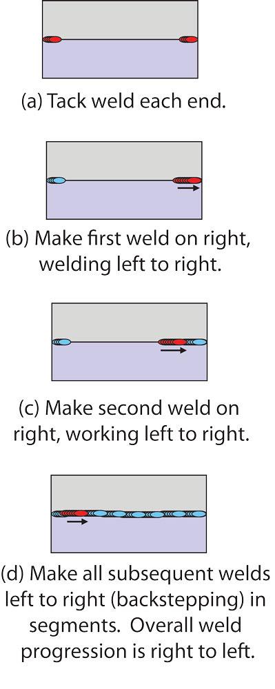
12. Use a backstep technique to limit rotational distortion. This principle only applies to prevention of rotational distortion (as shown in Figure 1 last month) and does not fix any other type of distortion. The technique involves tack welding of each end and then "backstepping" from one end about 2.5 cm and welding toward the end of the part (Figures 13a through 13d). After a 2.5-cm segment is welded, the next segment is deposited by backstepping, and welding toward the previously made segment. It does not matter from which end the backstep technique begins. Backstepping precludes the joint from opening or closing, eliminating the rotational distortion.
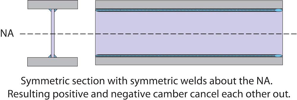
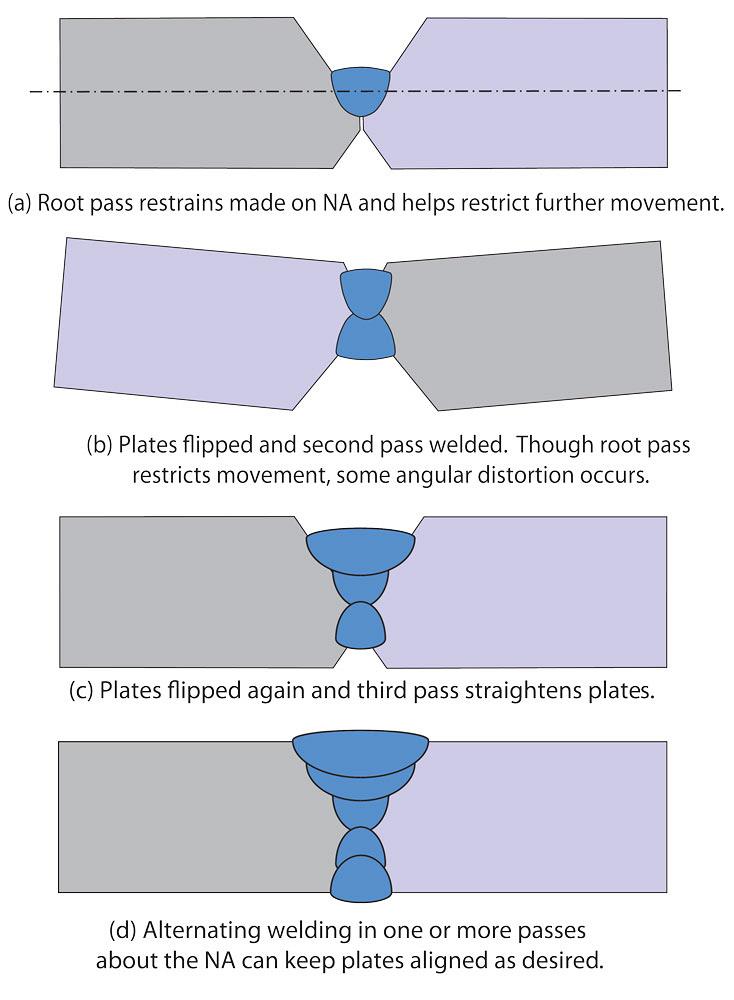
13. Balance welds about the neutral axis. This principle involves designing weldments with weld areas that are balanced about the neutral axis (NA) of the section. An example of this concept can be seen in a plate girder (Figure 14). Note that the four longitudinal welds are all symmetrical about the NA, and the distortion from each weld should cancel each other. Another example of this principle is the double-sided V-groove weld shown in Figures 15a through 15d. An initial root pass is made on the NA, which helps restrain the plates from subsequent angular distortion. The fill passes can be made, alternating on either side of the root pass, to maintain plate alignment. In this way, the passes are performed in a sequence to counteract each other.
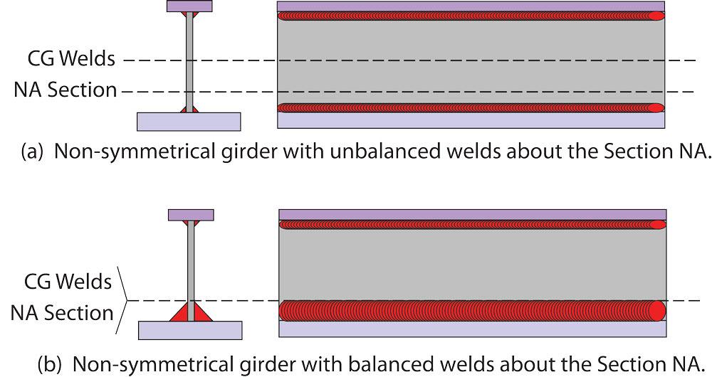
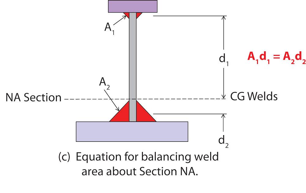
14. Balance weld areas about the neutral axis. When welds are not symmetrical about the NA, or when the weldment cross section is not symmetrical, adjust the size of the welds so that the NA of the section is concurrent with the centre of gravity (CG) of the welds. The non-symmetrical girder shown in Figure 16a is an example. Note that if all the welds are the same size, the CG of the welds does not align with the NA of the section. In this case, when the size of the bottom flange welds is enlarged, the NA and CG can be brought into alignment (Figure 16b) so that camber does not develop. Figure 16c shows the mathematics required to balance the CG of welds about a section NA.
15. Control assembly sequence. The sequencing of welds can have a dramatic impact on the final sweep or camber distortion of built-up members. Sequencing has the most impact on assemblies that are free to move while welding progresses but will have little to no impact on assemblies that are clamped in place.
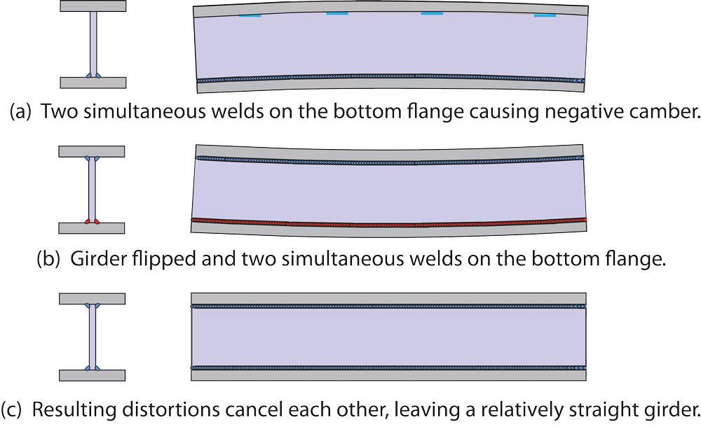
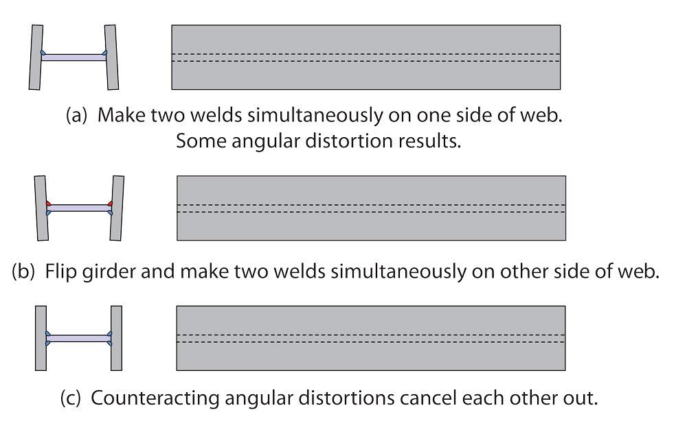
There are two basic sequencing concepts. The first deals with symmetry about a common NA. Welds should be placed in such a sequence that groups of welds mirror each other and the distortion from each sequence cancels each other out. For example, plate girders can be welded while the web is vertical (Figure 17a through 17c), or when dealing with deep webs, welding horizontal is often preferred (Figure 18a through 18c). In each situation, the correct sequencing straightens the girder out.
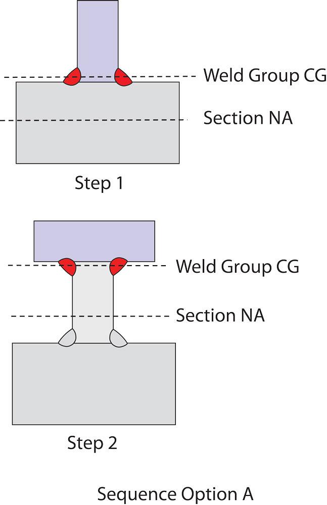
The second concept is that the sequencing of subassemblies should be done so that the CG of each weld sequence is placed on or as near as possible to the NA of the subassembly being welded together at that point in the process. For example, compare two sequencing options for a built-up girder, non-symmetrical about its strong axis.
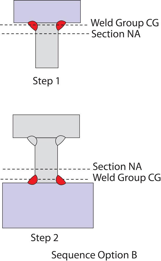
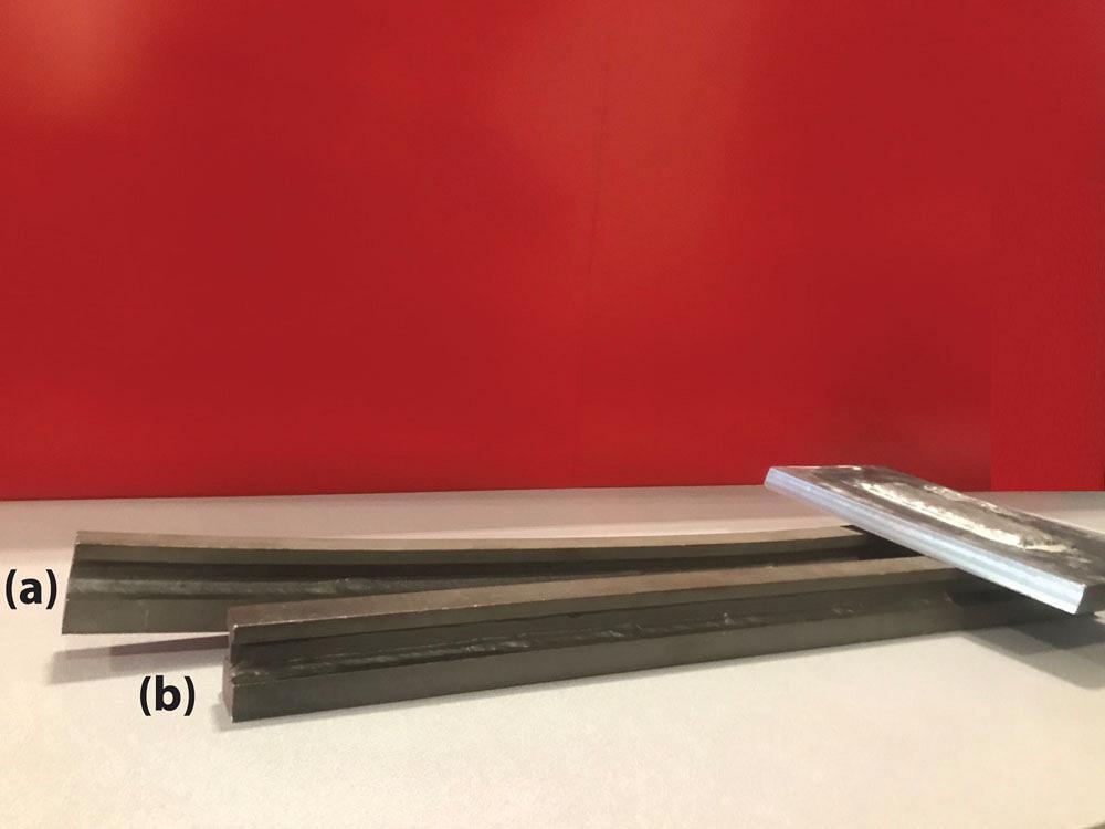
Figure 19 shows sequence option A, which leads to a significant level of distortion. Note that in each of the two steps of fillet welds, there is a significant distance between the weld group CG and the section NA. Furthermore, the weld group CG in both steps is on the same side of the section NA (above, in this case). Compare this to sequence option B (Figure 20); when we change the order of the welds, the weld group CGs are made closer to the section NA. Furthermore, weld group CGs are on opposite sides of the section NA, and what little distortion that exists from the two steps tends to counteract each other. Figure 21 shows a picture of an experimental specimen that was made with the two aforementioned sequencing options.
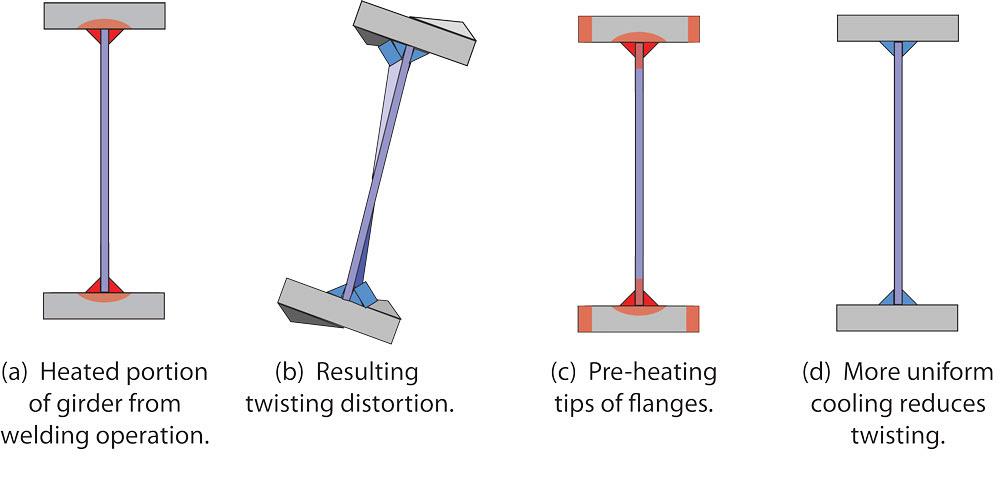
16. Use thermal tensioning. Thermal tensioning is a technique that can be used to mitigate twisting distortion on sections. Figure 22a shows the approximate distribution of heating on a plate girder and the resulting twisting distortion (Figure 22b). As the weld cools in these areas, it causes contraction and twisting. When heat is applied to the tips of the flanges (Figure 22c), the cooling and contraction at the extremities is the same as at the web/flange interface. The cooling and resultant contraction is uniform, thus reducing distortion (Figure 22d).
17. Peen the weld. When properly used, peening can help reduce the shrinkage in a freshly placed weld and thus help reduce the contraction forces that cause distortion. Some basic rules to follow for peening are that it should not be done to root passes or when the weld is too hot ("blue brittleness range") because the weld might crack. It should not be done when the weld is too cold because it takes too much effort to deform the weld. Peening should not be applied to the base metal because it cold-works the steel. Finally, surface layers of welds should not be peened because peening marks might mask weld defects and since it is the last pass, leave behind a work-hardened surface. If these basic parameters can be followed, then peening can help reduce distortion, but it is difficult to estimate how much distortion is averted.
18. Thermally stress-relieve the weldment. Thermal stress relief can eliminate up to 90 per cent of the residual stresses in a welded assembly. Residual stresses are what cause the elastic part of distortion. Thermal stress relief does not do anything to alleviate the permanent plastic part of the distortion, which is usually the larger problem.
Figure 12
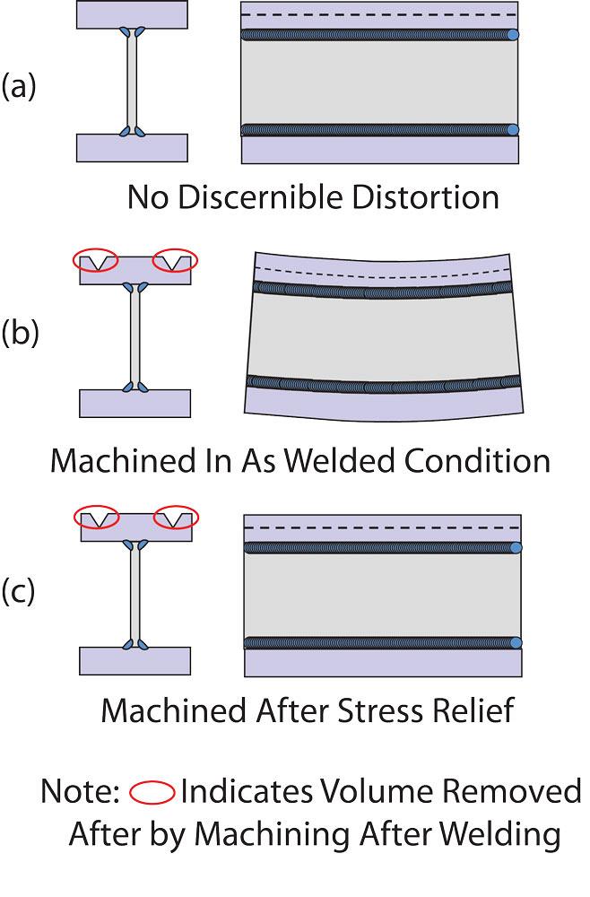
An important application of stress relief is on parts subject to fine machining. Consider a welded assembly with no discernible distortion (Figure 23a). During machining, material is removed from the assembly, changing its NA. This may cause "bounce back" of the part due to elastic rebound (Figure 23b). If the assembly were stress-relieved before machining, then the residual stresses that cause elastic distortion would be reduced by 90 per cent and probably eliminate distortion problems after machining (Figure 23c). If the elastic distortion after machining is still unacceptable, the part can be stress-relieved while clamped together. Clamping takes away the plastic distortion (see Principle 8), and thermal stress relief will help reduce the elastic distortion.
Though thermal stress relief can be used as a tool to reduce elastic distortion, it should be used with caution and evaluated in its totality because distortion can occur as a result of stress relief. While stress relief of welded assemblies that require precise dimensional control during machining is helpful, understand that stress relief will not change a distorted assembly into a straight assembly.
In this series of articles, the authors have explained what causes distortion in steel members due to welding, defined the different types of distortion, and provided 18 principles that can be used to minimize or eliminate unwanted distortion. It is imperative that engineers, fabricators, and erectors all take an interest in how steel members are welded together to meet the desired outcome for the final product.
Duane K. Miller is manager of engineering services, Curtis L. Decker is senior design consultant, and Charlie Cross is senior customer training instructor at The Lincoln Electric Co., 22801 St. Clair Ave., Cleveland, Ohio 44117, 216-481-8100, www.lincolnelectric.com.


Keep up to date with the latest news, events, and technology for all things metal from our pair of monthly magazines written specifically for Canadian manufacturers!
Start Your Free Subscription
Easily access valuable industry resources now with full access to the digital edition of Canadian Metalworking.

Easily access valuable industry resources now with full access to the digital edition of Canadian Fabricating & Welding.