Controlling Cutting Forces
Both axial and radial cutting forces can affect milling, creating chatter, burrs
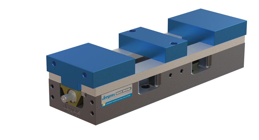
The Production Vise from Jergens has hard-coated aluminum bases, quick-change jaw system, and hardened and ground steel rails that help absorb vibration. Photo courtesy of Jergens.
To ensure your milling process goes well, it’s important to consider the workholding options.
And of course, when considering these options, it’s vital to take into account the cutting forces you’re dealing with based on the kind of milling you’re doing.
“The types of milling today are broken down into four main categories: face milling, shoulder milling, feed milling, and slot milling,” explained Thomas Hagan, milling product manager for Iscar Tools. “Cutting forces for various types of milling come from the characteristics of the material being machined, the type of milling operation, and the cutting tools.”
Cutting forces have two major components: axial and radial. Axial forces act in the direction parallel with the spindle. Radial forces act perpendicular to the spindle.
“Normally, the machine is rigid enough that it can handle all of the axial forces. In fact, we often design [indexable] cutting tools to generate more axial force than radial force because of this,” said Luke Pollock, product manager at Walter USA. “The radial forces are what cause us most of the problems. They try to push the tool off of center and are a primary culprit in causing chatter and not cutting to size.”
Unique Cutting Forces
Each type of milling has its own unique cutting forces.
Face milling typically is machining a flat surface over a single plane or a feature with small depth of cut. Usually it uses a low to moderate feed rate and moderate to high speed/RPM, creating the flat surface.
“Forces that are generated from face milling are axial to the spindle, with very minimal radial force. Using an insert that is 45 degrees on a face mill reduces the cutting forces overall into the part and elsewhere because of chip thinning. With all milling, forces can be reduced dramatically by climb milling rather than conventional milling,” said Hagan.
Shoulder milling creates axial forces against the tool and part.
“These forces are reflected by the depth of cut, width of cut, and chip load. The greater these values, the more forces. Chip load per tooth in shoulder milling can be problematic [when it gets high]. Tools can break, parts can move, and burrs can develop in the part, all from heavy forces inherited from high chip load. Less chip per tooth equals lesser forces on the side axis of the part, tool, and elsewhere,” said Hagan.
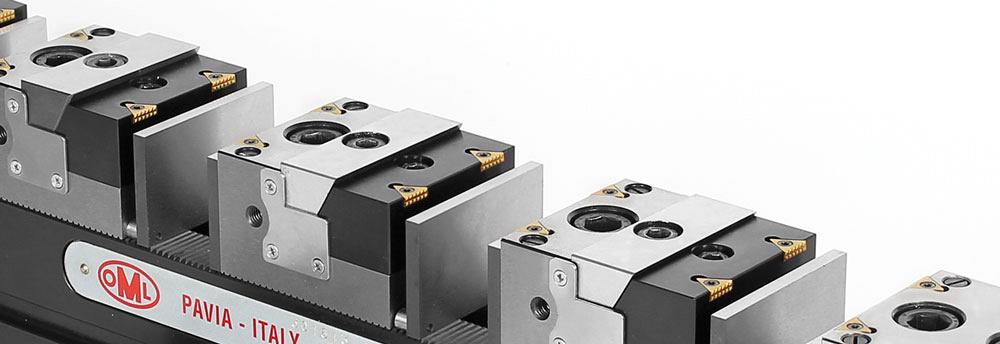
The TriMax C series from Fixtureworks can securely clamp up to four workpieces at one time. Photo courtesy of Fixtureworks.
Slot milling, meanwhile, involves forces all around the X, Y, and Z axes on the machine. It is the depth of cut and desired speeds and feeds that affect how the tool runs.
According to Hagan, feed milling is a combination of shoulder milling and face milling in terms of the cutting forces that are generated.
“Feed milling makes its gains on fast metal removal by minimizing forces generated typically with face milling and shoulder milling, and distributes them up towards the spindle, which is better suited to take the forces. The low depth of cut and geometry of the insert thin the chip, allowing for increased feed rates (chip load). Small cuts and fast feed rates maximize metal removal with allowable forces in the overall setup and operation,” said Hagan.
Materials Matter
Material properties that affect cutting forces include hardness, tensile strength, impact, and toughness, and each generates different levels of resistance and will require more or less force.
“Materials such as most heat-resistant alloys need lighter depths of cuts because the forces generated in those types of materials are far greater than in other materials. Also, they have tendencies to work-harden easily with heat being generated from higher cutting forces. Forty-five-degree cutters or positive cutting tool geometries are usually preferred to minimize these forces. The type of holder also plays a role in how the tool reacts with specific cutting conditions,” said Hagan.
Materials with higher tensile strength require more power to machine and so they generate more cutting forces between the tool and the workpiece.
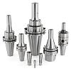
“To combat these forces, with regards to the toolholder, we try to look for a setup that is as rigid as possible. Steep taper holders such as CAT40 or CAT50 have good rigidity. However, the rigidity can be improved by using a variation that not only has contact on the taper, but also seats on the face of the spindle, causing a simultaneous fit on two different surfaces,” said Pollock.
While Capto®-style holding started primarily in turning, it also has become a more popular option in milling.
“Vibration control is a very important characteristic. The vibration control with regards to the holder is directly related to the quality of the connection to the spindle. Other important characteristics are runout and repeatability. Sometimes easy changeover time can also be important, depending on what the operator is trying to do,” said Pollock.
Controlling vibration is also key in terms of workholding.
“Any time you’re milling, you are constantly going from one tooth to the next. That creates vibration, especially in your finish milling passes,” explained Tim Easton, national sales manager of workholding for Jergens.
It’s important that any workholding be stable and strong. For a vise, this means having strong, dependable jaws.
“That’s where all the cutting forces and all the vibration are going to be absorbed into,” said Easton.
Common Mistakes
It’s important to avoid common workholding mistakes.
“One thing that we hear oftentimes is that a user is just not confident enough in their workholding or is unable to flesh out their workholding issues so that they can really crank up their machine. It’s all about holding onto their workpiece and feeling confident that they’ve got it secured properly. Once you have that confidence, then you feel a lot better about cranking up the spindle,” said Fixtureworks President Justin Gordon.
Another, similar mistake operators make is “not holding on to enough of the part … They’ll try to put it into a dovetail that doesn’t secure the part,” said Easton.
Needless to say, this might lead to a loose part and machining chaos.
This occurs “more with milling [when] you’re trying to take an excessive depth of cut or there’s excessive chip load at the milling face,” said Easton.
When it comes to milling, Hagan summarized the workholding facts of life.
“The better the workholder, the better the stability and rigidity. Shorter is better; this applies to the tool as well. The shorter the overhang on the tool, the better stability and rigidity, increasing tool life,” he said.
Contributing writer Nate Hendley can be reached at nhendley@sympatico.ca.
Fixtureworks, 586-294-1188, www.fixtureworks.net
Iscar Tools, 905-829-9000, www.iscar.ca
Jergens Inc., 877-486-1454, www.jergensinc.com
Walter USA, 800-945-5554, www.walter-tools.com
About the Author
About the Publication
subscribe now


Keep up to date with the latest news, events, and technology for all things metal from our pair of monthly magazines written specifically for Canadian manufacturers!
Start Your Free Subscription- Stay connected from anywhere

Easily access valuable industry resources now with full access to the digital edition of Canadian Metalworking.

Easily access valuable industry resources now with full access to the digital edition of Canadian Fabricating & Welding.
- Trending Articles
1
Automating additive manufacturing

2
Identifying the hallmarks of a modern CNC

3
CTMA launches another round of Career-Ready program

4
Collet chuck provides accuracy in small diameter cutting
5
Sandvik Coromant hosts workforce development event empowering young women in manufacturing