Turning up Micropart Production
Orders increase, part and tooling size decrease

An M4L 5xD from KSPT is a square end, 4-flute, micro endmill with a 1/8 in. dia. and 0.050 length of cut. Photo courtesy of KCPT.
Think about how small glaucoma pumps must be to be implanted on the surface of an eye. Those pumps need to be small enough to do their jobs without impeding normal eye movement. One report from German research firm Fraunhofer EMFT said that its glaucoma pump measures 7 by 7 by 1 cubic mm.
Think about how small the components must be inside that pump. An entire day’s production of one of those parts could fit in a coffee cup.Then take the thought process a step further and consider how small the tools need to be to make those microparts.
Not many years ago, they might have been produced in a shop with a bank of multispindle turning machines and, off in a corner or a clean room, one Swiss machine to make the small parts. Now, expanding focus on the tiny parts world and a proliferation of industries using miniscule parts, has prompted an expansion of companies dedicated to producing parts measured in millimetres.
Tools are Lasting Longer
Equipment to produce these tiny parts is continually improving and the tooling that this equipment needs to make parts is following suit. “It’s a bit like leap frog,” said Van Simpson, product manager of small parts machining for Vargus USA. “The machines themselves are getting more sophisticated and capable of performing operations at a high level of efficiency, quicker than ever before. Machine manufacturers develop new equipment operations; we develop new tools to support those capabilities.”
Constant upgrades to the carbides and PVC coatings used for microtooling help keep up with the machine tool upgrades. Regarding the carbide, Simpson said it’s a tradeoff. “It’s a bit of a balancing act. Do you want toughness or heat wear-resistance? Generally, the very things that make carbide tougher are at the expense of wear-resistance, but we’re always coming up with better grades of substrates and coatings.”
Microtool coatings, just a few microns thick, work in conjunction with the substrate. The coatings add a degree of lubricity to the chip interface and provide a chemically inert barrier between the substrate and the material being cut, significantly extending the life of the cutting tool.
As with standard-sized tools, the coatings may be multilayer. The final layer, often a gold colour TiN, helps improve performance and makes it easier to detect tool wear.
“A layering or combination of different materials can provide a general-purpose coating that has a wide application. It can create a coating that is effective when cutting a variety of materials instead of having a separate, specific grade of coatings for each material. We’ve made a lot of progress chasing the Holy Grail of providing one coating for all materials, but we’re not quite there. Some materials still require particular coatings for effective cutting,” said Simpson.
No Room for Error
Tools with diameters small enough to produce microparts have the same basic features and requirements for accurate cutting as their larger counterparts. Two areas where microturning tools have no room for error are the relationship to the centreline and the sharpness of the cutting edge.
Simpson said, “The relationship to center has to be right on. There is physically no room for error. And while a modest edge prep is sometimes advantageous, a sharp cutting edge is oftentimes necessary.”
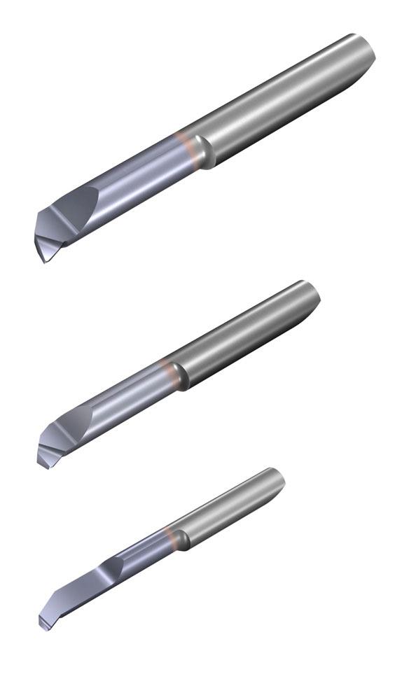
Solid carbide tools from the MicrOscope® line of Groovex tooling are for diameters from 1mm and up. Photo courtesy of Vargus USA.
Depending on the application, a little edge prep controlled in both size and shape, works. He said, “You want to be sure to have a consistent cutting edge, and a controlled edge prep can help achieve that. Some applications are further enhanced with the addition of a polished edge, or a modest chip former.”
It’s a Compromise
Ideally, once manufactured, nothing touches the cutting edges of the tools before they come in contact with the material. And the chips generated during the machining process, as fine as they may be, need to be thoroughly evacuated, which may require a chip-breaker on the end of the tiny tool.
“If you are cutting the inside of a part, for example a small-diameter bore, you may have chip clearance issues. The tools can have a chip-breaker on the end, but that addition can increase the tool pressure,” said Simpson. “You have some amount of tool pressure any time you cut, and you have to be extremely careful with the small-diameter tools. It doesn’t take a lot of excess pressure to generate chatter or even snap these small-diameter tools. Again, it’s a compromise. And these thin micro tools can extend a long way out from the toolholders and you can get chatter that translates to poor tool life and poor surface finish.”
A small, direct stream of coolant delivered to the interface of the workpiece and the tool can help keep the temperature down and assist with chip evacuation. Surprisingly, some small-diameter, solid-carbide tools are through-coolant.
“Our ability to get through-coolant in small-diameter tooling has improved,” Simpson said. “The diameter of a tool depends on the operation, but through-coolant is available in tools under 1/8 in. diameter.”
Creating Tiny Features
The bulk of the work for microparts is accomplished by the turning heads of the machining centres, but then the very fine features need to be added. Tools that are no bigger than a human hair, 0.005 in. dia., accomplish functions like cross-milling to create these features. One thing that makes this tooling unique is that is begins with a common shank size and tapers down to the miniscule diameter at the working end. The tapering gives the tool more working strength.
“These tools are very small and create features for very small parts,” said Brian Hamil, vice president of product development for Kyocera SGS Precision Tools, (KSPT). “When it comes to the production of these features, the micropart’s physical features will be much more uniform if humans aren’t involved. The part will be a higher quality if it doesn’t move from fixture to fixture or machine to machine. This type of production needs a very controlled environment where the raw material enters the machine and completed parts exit.”
Tools to add these features approach the milled part from the end or the side of the part.
“The machines can typically position the part within about 270 degrees without reclamping,” said Hamil. “So milling can be done, the features can be made, and the completed part cut off from the bar stock in one operation. There are 2-flute, 4-flute, and ball nose tools to create these features. There are tools that will cut a diameter with a corner radius,” he said.
Coatings Here, Too
Coatings are also important for these tools.
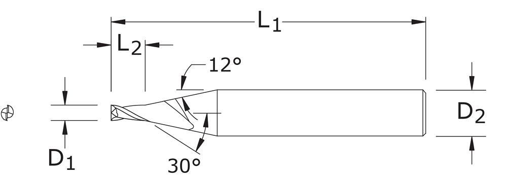
M4L 5XD tool from KSPT dimensions are: cutting diameter, D1, 0.010; shank diameter, D2, 1/8 in.; length of cut, L2, 0.050; overall length, L1, 2 ½ in. Illustration courtesy of KSPT.
“When coatings are added we’ve found an improved tool life even for the extremely small diameter tooling that runs at 50,000 RPM. The coating is harder than the carbide substrate and offers a lower coefficient of friction so there is some abrasive wear protection. The coating’s lubricity rejects material that wants to adhere to the tool and the coating increases the hardness of the cutting edge which contributes to tool life.
“You have to have a tremendous amount of RPMs to generate surface footage using these tiny tools,” he said. “And you need a certain amount of lubricity so the material and chips being cut won’t adhere to the tool.”Once a tool is worn, it is done. The process of regrinding and recoating a tool that small wouldn’t save anyone any money said Hamil.
The manufacturers involved in this type of machining are used to dealing with microscopes and magnifying glasses. They know how to handle—or not handle—the tooling.
Hamil said, “Manufacturing environments and their treatment of the micro-tooling vary depending on the application of the parts being made. I’ve seen a manufacturer run parts until they broke [the tool] because he said it was too hard to predict the failure. And I’ve seen very structured environments where the shop predicts tool life and changes tooling based on that predictability. They may get a whole shift with one tool or just a specific number of parts. It just depends on the material being cut.”
Kyocera SGS Precision Tools, 330-688-6667, www.kyocera-sgstool.com
Vargus USA, 800- 828-8765, www.vargususa.com


subscribe now


Keep up to date with the latest news, events, and technology for all things metal from our pair of monthly magazines written specifically for Canadian manufacturers!
Start Your Free Subscription- Stay connected from anywhere

Easily access valuable industry resources now with full access to the digital edition of Canadian Metalworking.

Easily access valuable industry resources now with full access to the digital edition of Canadian Fabricating & Welding.
- Trending Articles
1
Automating additive manufacturing

2
Identifying the hallmarks of a modern CNC

3
CTMA launches another round of Career-Ready program

4
Collet chuck provides accuracy in small diameter cutting
5
Sandvik Coromant hosts workforce development event empowering young women in manufacturing