


Trending towards special bending
Experienced tooling engineers welcome but not required

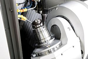
A large gooseneck punch and tall radius tool are examples of tools designed for specific applications.
History has taught manufacturers that bending a complex part requires three things: an accurate press brake, an experienced operator, and carefully chosen tools. Current manufacturing practice demonstrates that as parts continue to become more complex, it is increasingly difficult to convert from 2-D to 3-D components. These realities have helped propel original equipment and tooling manufacturers into the heart of Industry 4.0 with a focus on making the bending process easier and tooling selection, design, and delivery faster.
Advanced technology has tightened Ty and Tx tolerances to increase machine tool precision. Intuitive software packages are being developed to make precise bending less reliant on operator experience, as replacements for retiring bending artisans are difficult to find. Standard tooling has become more versatile, functioning with various materials and producing a larger variety of bends. Still, there are configurations for which a manufacturing engineer or operator must determine if special tooling is needed to get a job done. The application might call for a special tip radius, working height, or a cutout area to avoid collision during the bending process.
Uncomplicating Complex Parts
“We are producing more and more specials because parts are getting more complicated,” said Gunter Glocker, president of WILA USA. “In alignment with the Industry 4.0 trend, we developed Tool Advisor, an engineering tool to support the engineering processes of fabricators, press brake builders, and distributors. It helps select the best tools for a job and, when it identifies the need, helps design the specials.
“A tooling buyer can enter the specifics—the tonnage, working height, ram stroke, and so on--of the press brakes they have. If they don’t want to do that the program defaults to the parameters of a standard press brake. If they want to take advantage of the software’s full capabilities, they can enter any WILA tooling that they already have. The more specific the information provided, the better the tooling advice that can be given.
“The next steps are entering the material type and thickness; they can also draw the critical bends of the part profile in a 2-D format. The software will give them a selection of standard tools that will work for the application. If it is aware of the company’s tool inventory, it will evaluate and suggest those tools before making purchase recommendations. Different criteria--like which is the most flexible tool, working height, or lowest cost--can be used to search and select the tools for purchase. A price and delivery time for the tool are given once the software is provided with the tool length and how it is to be segmented.
“The Tool Advisor software is connected to our Webshop software, which actually prices everything automatically, even special tools, and calculates the formal quote while online. Real-time availability and delivery times are also automatically calculated. If the tooling is then ordered, all of the critical information is captured and provided to manufacturing.”
Making it Special
The software also offers the opportunity to design a special punch if a job can’t be done with standard tooling.
Glocker said, “Some fabricators already know what kind of special tool is needed. Let’s say they are forming a deep box and they know they need a tall punch. They can specify a 12-inch height as part of the tool design parameters. Or if the part is soft aluminum that forms around the punch, a special tip radius might be needed. Certain design criteria such as working height, radius, and bend angle can be modified.”
Design assistance is built into the program. The software will walk the designer through the process and create an alert if the punch configuration might present a problem. For example, if the tool is too weak, a message is generated to inform the maximum load capacity of the tool. That information then can be taken into account for the type and thickness of the material to be formed. The design will not be accepted for production until the punch is strengthened.
“Let’s say a bottom die is too wide to accommodate a very tight down flange. The interference will be seen, and the software will recommend narrowing the width of the die on the back side or both sides so the part can be formed. Any place that a tool will interfere with a part will be detected, and recommendations as to how the tool can be modified to form the part will be provided.
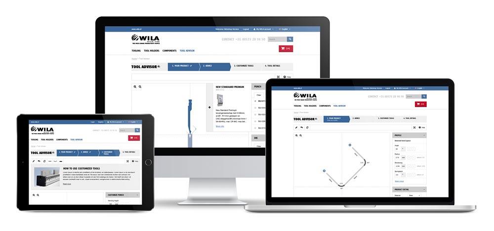
WILA’s Tool Advisor provides guidance in designing special press brake tooling.
“For example, if you are working with a stainless part or other high-tensile material that has a lot of springback, which can collide with the upper punch, the software will show how to move the centerline back and how to restrengthen the tool, which has been weakened by adding material to the backside of the punch.”
Human review of special tooling designs is also involved. Before an order is processed and heads to production, the design is reviewed by the engineering department.
“We give the information from the Tool Advisor to production engineering so they have all the parameters from the tool quotation, and once checked and approved, it can go directly on to manufacturing.
“The main ideas for developing these interactive software packages were to make designing and ordering easy and to speed up turnaround time.”
Tooling that Communicates
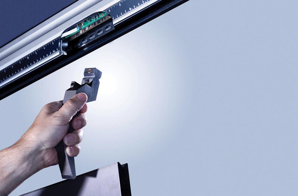
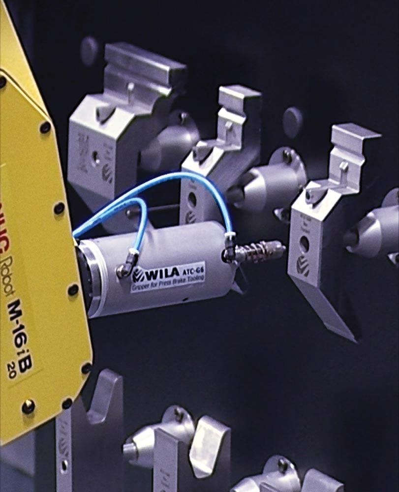
A move away from conventional brake setup to automatic tool change (ATC) is also high on the list for making precision bending easier and faster in the 4.0 world. To make ATCs work, the automation needs a way to easily locate and identify the specifications of each tool.
“We are building what we call intelligent tooling. Electronics that are built into the tooling and tool holders provide information in a closed-loop system for use with the automation,” said Glocker. “Basically, the information is embedded in an identification chip with all the tool data—profile, angle, work height, maximum load, segment length—everything about the tool. An ID chip will be on the back and front sides of the punch tang so the tool can also be reversed, like for a gooseneck punch. The upper clamping system or bottom tool holder has an electronic strip to gather the information from the tool. A DIN controller communicates with the press brake control and routes the information.”
“When programming a robot to setup to produce a certain part with certain tools, the system can find the correct tools in the storage system and exactly place those tools in the brake. It is very easy for the robot to go right to the tool’s position, pick it up, and load it into the machine,” Glocker said.
“Parts are getting more and more complicated, and lot sizes are getting smaller. By the time a part gets to the press brake, it already has a lot of added value. If a fabricator has a lot size of one or two, or even 20, it can’t afford to bend a part wrong. The companies that are going to stay in business are embracing the technology that makes it more efficient for them to do short-run work productively.”
Photos provided by WILA USA, 443-459-5496, www.wilausa.com

subscribe now


Keep up to date with the latest news, events, and technology for all things metal from our pair of monthly magazines written specifically for Canadian manufacturers!
Start Your Free Subscription- Stay connected from anywhere

Easily access valuable industry resources now with full access to the digital edition of Canadian Metalworking.

Easily access valuable industry resources now with full access to the digital edition of Canadian Fabricating & Welding.


