Associate Editor
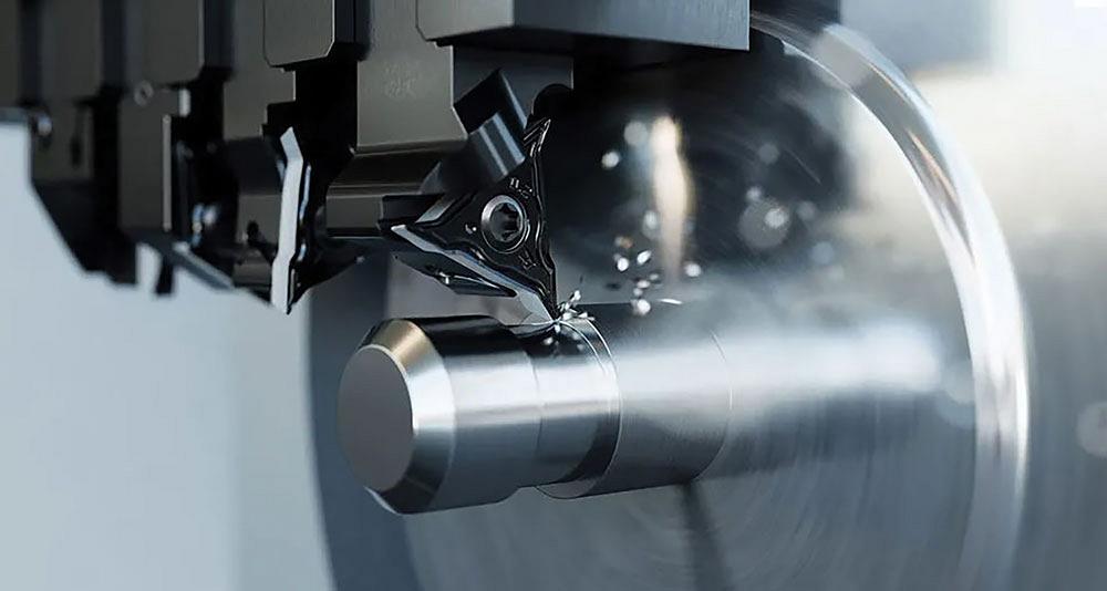
If your workpiece has a complicated profile with varying features, like a chamfer, undercut, taper, or curves, you will need multiple axes of motion. Walter Tools
In traditional turning operations, the cuttings tool moves towards the chuck and spindle rather than away from it. This is because, typically, the cut should always travel in the strongest direction. A typical setup will feature a chuck, which is where the workpiece is held tightly, which is the strongest part of the machine tool. All of the cutting forces are absorbed in the axial direction into the chuck and spindle of the machine.
“Turning (OD) and boring (ID) are terms used to change the diameter of a plain cylinder (OD) or hole (ID),” said Ken King, chief operating officer, THINBIT, Fort Wayne, Ind. “In profiling operations, the cutting tool is used to create shapes and complex grooves in a workpiece. Profiling and turning/boring operations are similar operations. Generally, we define reverse profiling as moving the cutting tool away from the chuck or collet while cutting.”
In many cases, the part itself will determine if reverse profiling makes sense. If it’s a simple cylindrical workpiece that requires the removal of 0.05 in. of material, then it doesn’t make sense to profile.
“If it's a complicated profile with varying features, like a chamfer, undercut, taper, or curves, all of these features on a workpiece typically suggested that you will need multiple axes of motions,” said Sarang Garud, product manager, turning/drilling/boring, Walter Tools, Waukesha, Wis. “This is where reverse profiling makes sense. It’s also very common for ID boring to have internal profiles, so we see reverse profiling in those applications too.”
There are many advantages of reverse profiling. For example, in many cases, a V-style insert is used for profiling. These diamond-shaped inserts are very sharp and have a very narrow 35-degree included angle.
“When profiling, you are using the 35-degree angle going towards the spindle, using one cutting edge,” said Garud. “When reverse profiling and moving away from the spindle, you are using the other cutting edge. That’s a significant tool life advantage. Secondly, it can save a lot of time because you are not rapiding out then coming back in.”
King added that while both types of profiling have equal cutting parameters, the biggest drivers for choosing reverse profiling are chip evacuation and finished part geometry.
For example, many components requiring complex profiling, including contours, chamfers, and undercuts, tend to be produced at high volumes where there is a high demand for reduced cutting time.
“There is tooling designed to both profile and reverse profile,” he said. “This is known as multidirectional profiling. If this method is employed, cutting cycle times can be reduced.”
The challenge with using reverse profiling is ensuring that the workpiece doesn’t get pulled out of the chuck from the axial forces. Part geometry and setup play significant roles in determining if reverse profiling makes sense.
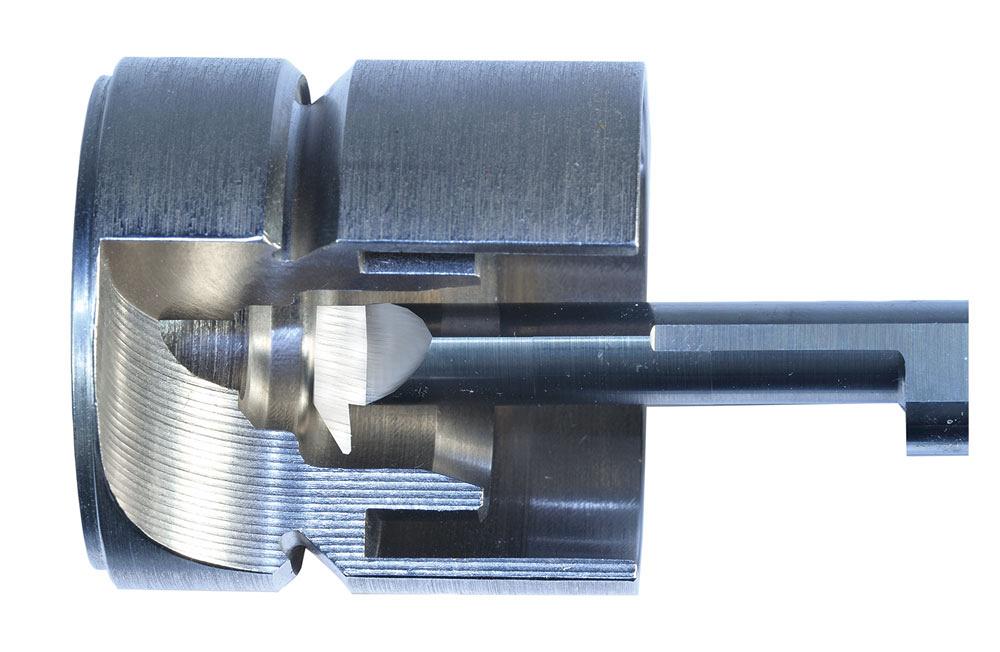
While both types of profiling are equal in cutting parameters, the biggest drivers for choosing reverse profiling are chip evacuation and finished part geometry. THINBIT
“It’s really an opposite thought process for programmers and operators,” said King. “Pull from chuck versus push toward the chuck changes axial forces, and chips flow differently. Reverse profiling pulls on the part and pulls on tools, which could result in pulling the cutting tool out of its holder or pulling the stock out of the chuck.”
This is why setup is one of the biggest factors determining success for reverse profiling. Without a strong and proper setup, both the tool and workpiece face forces that can make this operation impossible to complete.
“Machine tool capabilities are important to understand,” said Garud. “On the hardware side, a rigid setup is important. You don’t want long overhangs. The rest of it can be managed through depth of cut, corner radii, and basic process parameters. A CAM program also will likely be necessary. If it is a simple undercut, this can most often be done manually. But typically with profiles, the complexity requires a good CAM system.”
The experts agree that reverse profiling is often associated with ID work. Part of the reason for this is because chip evacuation can be challenging in a bore. Birdnesting that occurs on the OD is manageable. However, with birdnesting that occurs with ID work, chips don’t easily come out and you risk damaging the insert because it will recut the chips.
“Reverse profiling is very good for avoiding chip packing in blind bores,” said King. “It also makes chip evacuation easier as it naturally directs chips out of the bore.”
Lead angle plays an important role in chip development. For applications using a V-style insert with a conventional profiling lead angle is 107.5 degrees, that lead angle suddenly becomes 35 degrees with reverse profiling.
“This tilts the cutting edge quite a bit, which means that chips become very thin using that same feed rate,” said Garud. “To make up for that chip thinning, the feed rate needs to be increased, almost sometimes 50 to 60 per cent higher than traditional profiling. This can be an advantage because you are taking out material that much faster and potentially expanding the tool life using both sides of the insert.”
The depth of cut with any type of profiling tends to be much smaller than roughing, medium, or finishing depth of cuts. However, the depth of cut should be more than the corner radius of the insert.
“There are a few things to watch out for,” said Garud. “It’s important to be careful when going up to a shoulder when moving away from the spindle. You also have to manage the exit of the tool so that you are not crimping chips between the shoulder and the insert. Depending on the condition, you can back off from the cut in a 45-degree angle when you are rapiding out. Then you can come back and do a finishing pass later, especially if you have multiple passes going toward the shoulder.”
King also noted that there are a number of other considerations to keep in mind for success.
“If coolant is used, it should always be applied to direct chips away from the cutting area,” said King. “Cutting geometry is on the trailing side of the cutting edge, which also is the side of the toolholder body. Cutting depth and chip clearance all need to be verified.”
Associate Editor Lindsay Luminoso can be reached at lluminoso@fmamfg.org.
THINBIT, www.thinbit.com
Walter Tools, www.walter-tools.com


Keep up to date with the latest news, events, and technology for all things metal from our pair of monthly magazines written specifically for Canadian manufacturers!
Start Your Free Subscription
Easily access valuable industry resources now with full access to the digital edition of Canadian Metalworking.

Easily access valuable industry resources now with full access to the digital edition of Canadian Fabricating & Welding.