Associate Editor
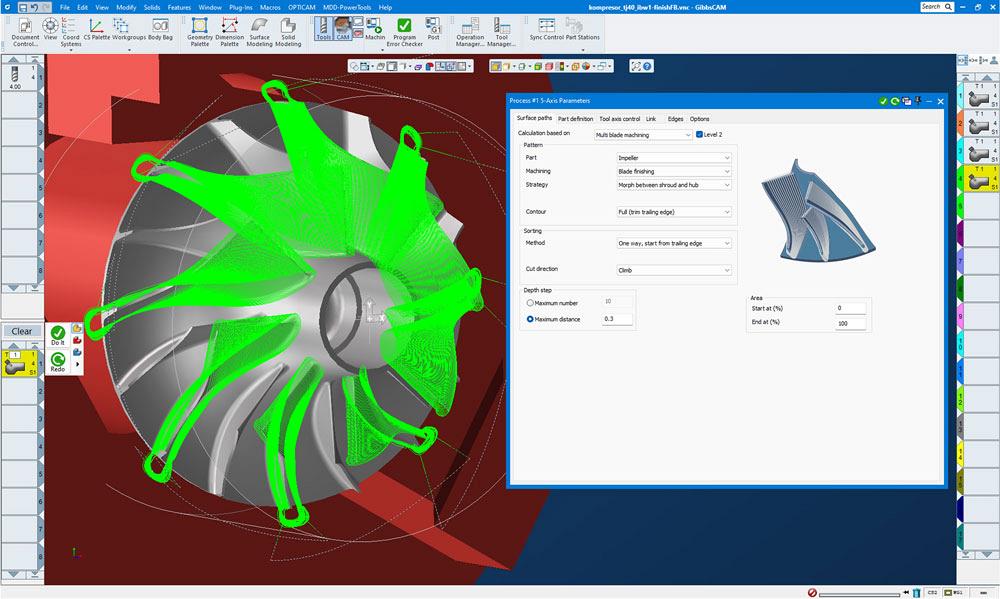
Selecting toolpath strategies is ultimately up to the programmers, and with a myriad of technologies and modules available, it’s important to understand which strategies are going to work best for the application. GibbsCAM
Programming complex 5-axis parts is a skill often developed through years of experience. As new programmers and machinists come into the workforce, a lot of that tribal knowledge no longer exists, and best practices may not seem obvious. There are a few starting points to help make toolpath creation easier and more intuitive. From there, programmers can use the latest technology to reduce time between design and finished parts and optimize the machining process.
“A good starting point is selecting CAM software that is easy to learn, especially if personnel are relatively new,” said Daniel Remenak, product manager, GibbsCAM, with Cambrio in Cincinnati. “The second point is practice and training. Learn from people who know how to do it well, and then practice that. There is an art to getting good toolpaths with 5-axis machining.”
Many CAM providers offer training and tips to help shops move into 5-axis machining. However, ultimately, every part is different, with huge variation in specifications and requirements.
“At first, it can be a lot of trial and error, but one of the nice CAM features that can be helpful is knowledge-based machining with the ability to store strategies once you’ve created them,” said Marc Bissel, senior applications specialist, CAMWorks, Scottsdale, Ariz. “It may take experience to determine the best toolpaths and the best way to create the toolpaths, especially when it comes to 5-axis machining as there are a lot of parameters involved.”
The goal in part production is to create complex parts effectively and efficiently. It’s important to leverage all tools available to make this process smooth and quick. The faster good parts get out the door, the better.
“It’s not just about selecting good cutting tools, but also choosing good fixturing, coolant, software like CAM or verification,” said Dave Miller, manager of sales engineering, strategic/key accounts, Mastercam, Tolland, Conn. “All of this can be done upfront and ahead of time so as not to complicate or expand the process. Keep everything as simple as possible.”
To maximize material removal rates, especially with 5-axis machining, it’s important to simplify the process as much as possible. There are some strategies that help reduce cycle time and make machining more efficient.
“When you get into 5-axis on any software, there's so much more at your fingertips and ways you can approach cutting a part that it can be difficult to know where to start and how to proceed,” said Miller. “End users and machinists will get into different ways to utilize the same toolpath. One toolpath might be used in 25 different applications in different ways. It’s not always obvious what toolpath should be selected or how it should be applied. But there are some new techniques that should definitely be explored.”
Just because you have a 5-axis machine doesn’t necessarily mean 5-axis motion is the most effective approach.
“Using 3+2 machining for roughing is a great place to start,” said Bissel. “3+2 machining for finishing also is becoming increasingly more common, and when possible, it can be advantageous and helps reduce the cycle times on the machines as well.”
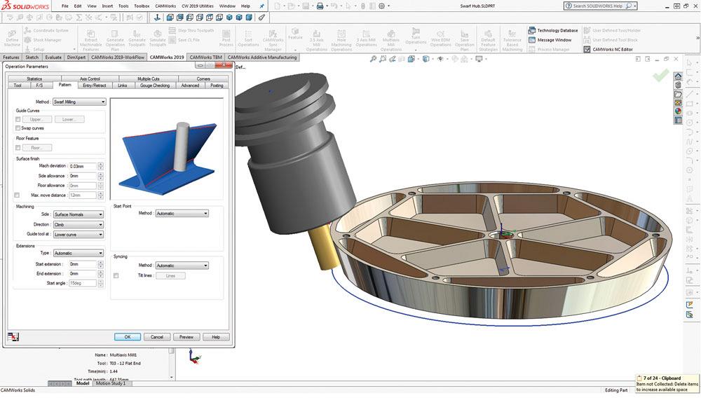
Swarf milling can greatly reduce cycle times, especially on finishing of complex or NURBS surfaces. With this technique, the side of the tool is used to perform finishing operations rather than a ball nose or a barrel tool. CAMWorks
VoluMill for high-speed roughing is another option. This module combines optimal milling paths and maximum material removal with minimized machining times and has been integrated into a number of different CAM systems.
“Science-based toolpaths don’t necessarily get used as often as they should,” said Remenak. “These are high-speed milling toolpaths that includes VoluMill. These toolpaths monitor the volumes and forces that are involved in the cutting and generate toolpaths that sustain extremely high removal rates. That's the best way to kind of raise your removal rate during roughing.”
While there are some great strategies for maximizing metal removal rates in roughing, finishing is often the most time-consuming segment of the machining process, which is why CAM manufacturers have focused on developing modules to help with this.
“Accelerated finishing technology is a cutting method that delivers a higher quality surface in less time than traditional finishing techniques,” said Miller. “This technique is relatively new in the industry, as the software is catching up with the latest cutting tool shapes and geometries. This strategy leverages cutting tools in a way that we can drastically speed up finishing cuts on free-form surfaces and drastically cut your cycle time.”
An example of this is using circle segment cutters or barrel mills, which according to the experts has been one of the biggest gains in recent years. These tools need to be used in 5-axis but can be somewhat difficult to program. These tools have a large radius on the side or taper of the tool so it can be much larger than traditional tools and can take fewer passes while maintaining a good surface speed. CAM software with modules or technology to take advantage of these tools is helpful.
“You can keep cutting speeds up, but it’s important to maintain the contact point on that large radius on the side of the part,” said Remenak. “This means that all the angles have to be right in order to get that surface finish.”
Bissel agrees that barrel mills are great for finishing 3- through 5-axis non-uniform rational B-splines (NURBS) surfaces. However, he noted that swarf milling also can greatly speed up finishing of complex or NURB surfaces, reducing cycle times. With this technique, you use the side of the tool rather than a ball nose or a barrel tool
Post-processing is that step that makes the process manufacturing. Everything up to this point in the process is not real, or at least not in the real world. Post-processors post code, which is generated instructions for the machine to actually do the cutting.
“It's really important that your post-processor is accurate and tested properly,” said Remenak. “Always test your post-process yourself. Come up with a part that represents the kind of work you do and test your post-processor. Make sure that you're getting the work plane output that you expect and the inter-operation motion that you expect. The truth is, even your machine doesn't necessarily know all the details of your machine, especially with different factory-set parameters.”
A lot of that variation can be unknown or difficult to figure out, and you can’t rely on what you think you know. A post-processor is specific to the machine and needs to be dialed in to ensure an edit-free G-code program.
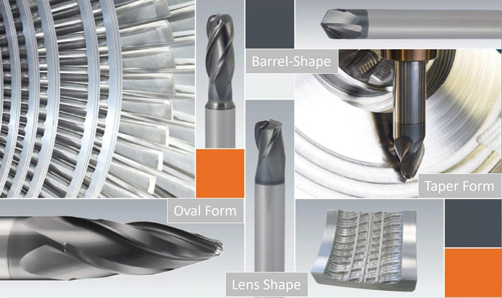
Accelerated finishing technology delivers a higher-quality surface in less time than traditional finishing techniques using the latest cutting tool shapes and geometries. Mastercam
“With 5-axis machining, post-processors need to support the tilted work planes using G68.2, for example, which greatly simplifies 3+2 programming,” said Bissel. “The G68.2 support is critical for the post. Likewise, it also should support tool center point control (TCPC) and dynamic work offset (DWO). All of these are techniques that are used for programming and can greatly reduce the programming time and simplify programming of parts and setup.”
Bissel added that a post-processor should also include tool normal vectors output using IJK vectors or Euler angles to promote sharing of the program between machines, making it easier to transfer from one machine to another using a particular Euler angle versus TCPC or DWO, which can be machine specific. It just depends on whether the machines support those or not. The Euler angle is more universal.
“It's unfortunate in some ways that there's never been really a standard set for G-code,” he said. “Most machines now follow certain standards, but then you also have European machines, the Siemens controls, and others that do things differently or use different codes.”
The best way to maximize and leverage the capabilities of the post-processor is to work with your CAM developer to ensure accuracy.
“We always recommend that changes take place in the CAM system where you can see the results, verify the results, test the results, before you get to the machine,” said Remenak. “If you're editing code on your machine, I don't care how careful you are, at some point you're going to make a mistake and crash your machine. It's important that you test your post, understand your post, trust your post, and do all changes before it gets to the post.”
In many instances, post identifies and adjusts the program for singularities—parts of the program with very slow motion on the machine because the machine is moving around a fixed point so the tool starts to move slowly.
While it’s true that in many systems, the post is responsible for resolving singularities, in some CAM software like GibbsCAM, this is not the case. All kinematic solving, including singularity resolution, is done in the software during the programming phase, where the user can control and verify it. Sometimes the best way to avoid singularities might even be to set up or fixture the part differently.
“Also, there is a tendency to underestimate the amount of time that the machine spends in the air,” said Remenak. “Understanding how to transition between cuts quickly is also important. Using something like clearance volumes will help transition close to the part and at high speed safely. That can really help shave down a lot of the time that a system less aware of the machine kinematics might instead choose to go home because that's the only thing they can do safely. But at that point, you're wasting a lot of time rapiding away from the part, rapiding back towards the part.”
This is where simulation comes into play. With 5-axis machines with complex parts and complex tooling on them, accurate machine simulation directly from the G-code becomes essential.
Once you've generated the toolpath, it's important that you can verify it and make sure that the machine is going to run as expected and not create awkward motion during singularities. This is where accurate machine simulation is essential.
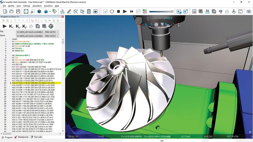
Having accurate G-code simulation directly from the G-code, like with CAMWorks Virtual Machine, keeps the CAM system from introducing errors in the code. CAMWorks Virtual Machine shows the G-code used to run the 5-axis mill on the left, and full machine simulation with collision detection and error checking is in the graphics area. CAMWorks
“With any machine toolpath, most users will start running a single step through with a program and make sure it cuts properly on a basic toolpath,” said Miller. “It might be 50 lines of G-code. You can single step through it pretty easily, but when we're on a 5-axis style toolpath, it might be thousands or millions of steps of toolpath. That's where simulation comes into play, where the more that you can simulate and prove out on the computer side before you even get out to the machine, the more the chance that you can hit that green button and be confident that everything's going to work without crashing that machine.”
The CAM system and the post-processor need to work together to generate good G-code. The CAM system can introduce errors into the G-code that you won't see until you get to the machine. Having accurate G-code simulation directly from the G-code, like with CAMWorks Virtual Machine, eliminates that possibility and can save a machine from being crashed or expensive tools from being broken.
To ensure that result, the software needs to know the kinematics of your machine, and you need accurate models and setup data. The accuracy of your machine simulation depends on the accuracy of your setup.
“If you tell the software that your part is on the middle of the table, but you set it up on the edge of the table, you're going to have very different results,” said Remenak. “The machines are capable of compensating and you just have to be aware of how much error you're introducing with that compensation.”
Another important thing to watch out for is in the CAD models. Is the part being programmed and machined to the mean of the tolerance? Modelling to the mean is an important design for manufacturing practice and critical for 5-axis complex parts.
“If a tolerance on a part is +0.005 in. and -0 in., we don't program it to the 0 (or the low); we program it to the mean,” said Bissel. “In this case, the mean would be 0.025 in., halfway in between the two, so that it falls right in the middle of the tolerance that's available.”
The design intent is for the highest-quality part to be right at that mean dimension. It also gives you the most room on both sides of the mean to keep the part within tolerance. If the tools start to wear a little one way or the other, this gives you more room to compensate for that wear and still have a good part.
“The models are often not modelled to the mean; they might be modelled to the low or high depending on how the engineer does it,” said Bissel. “Oftentimes, the engineers will model OD features to the low and ID features to the high to make sure a mating part will fit, but this can be a problem. The models need to be accurate and to the mean of the tolerances.”
Associate Editor Lindsay Luminoso can be reached at lluminoso@canadianmetalworking.com.
CAMWorks, camworks.com
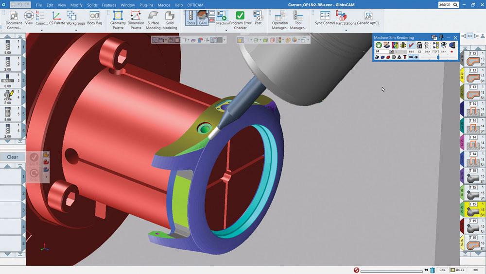
Once you've generated the toolpath, it's important that you can verify it using simulation to ensure the machine will perform as expected. GibbsCAM
GibbsCAM, www.gibbscam.com
Mastercam, www.mastercam.com


Keep up to date with the latest news, events, and technology for all things metal from our pair of monthly magazines written specifically for Canadian manufacturers!
Start Your Free Subscription
Easily access valuable industry resources now with full access to the digital edition of Canadian Metalworking.

Easily access valuable industry resources now with full access to the digital edition of Canadian Fabricating & Welding.