


Editor
To help insert recognition, the American National Standards Institute (ANSI) developed B212.4-2002 to allow machinists, purchasing departments, and tooling sellers to quickly and easily describe the shape, dimensions, and important parameters of turning inserts.
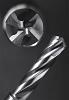
Turning on a lathe is an operation in which a stationary single-point cutting tool meets a rotating workpiece to produce axially symmetrical shapes. Sounds pretty easy, right? Well, it typically is, if the correct cutting parameters and inserts are chosen for the job.
Insert choice requires taking into consideration a whole host of variables, including an insert’s size, shape, and overall design features. In most cases, the tool is held in a fixed position in a tool body and the workpiece rotates in the lathe’s turning axis.
The success or failure of a turning job often depends on decisions made early in the process -- before the cutting even begins -- about a small piece of carbide, cermet, ceramic, or diamond.
Whether the application calls for rough turning, medium turning, or finish turning, the decision on what technology to use should come well before the material is loaded onto the machine or into the bar feeder.
Single-point cutting tools remove workpiece material by using one of the insert’s cutting edges. But how do you differentiate one insert from another? It starts by understanding their designation.
To do this it’s important to have at least some understanding of the American National Standards Institute (ANSI) turning insert designations. ANSI developed this system of numbers and letters (B212.4-2002) to allow machinists, purchasing departments, and tooling sellers to quickly and easily describe the shape, dimensions, and important parameters of turning inserts. It essentially gets everyone on the same page.
For turning inserts, it comes in the form of a 10-place string of numbers and letters, (the first seven are required and the last three are optional), with each describing a portion of the tool.
A common turning insert, for example, is a CNMG432.
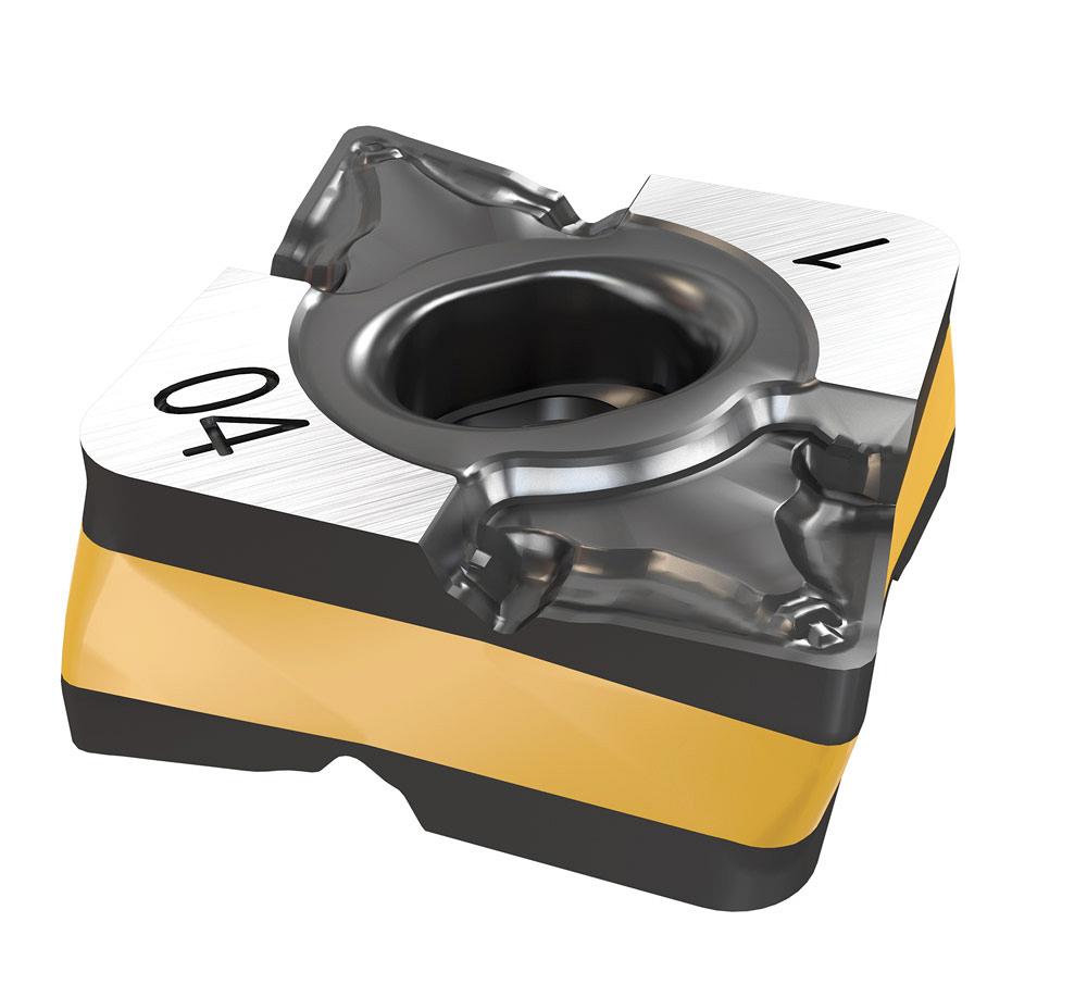
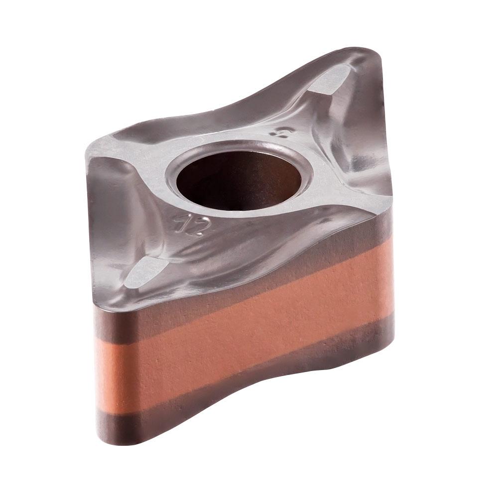
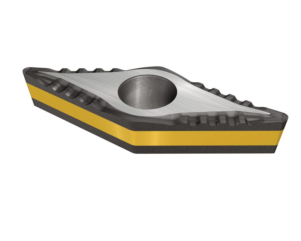
The first place shows the shape of the insert. There are 17 standard indexable insert shapes, and each is given a capital letter. In our example, C indicates that the insert is a rhombic-shaped insert of 80 degrees.
Some inserts, like round ones (R), have high edge strength, while some rhombic-shaped inserts (D and V) have a sharp point, which is good for finishing operations. Trigonal inserts (W) often are used for rough machining because of their larger point angle. Each has its place. The shape of the insert also determines how many separate edges can be indexed to as each wears out. The common insert shapes are:
Insert measurements and tolerances can get tricky and change based on the insert's shape, so it’s a good idea to consult the literature that accompanies your tooling purchase to get this right.
Also known as the clearance, the second place shows the angle between the flank and top surface of the insert. Each relief angle is denoted by a capital letter. In our example, the insert has a 0-degree relief angle.
The space provided by this clearance keeps the insert from rubbing against the part. If the insert does have a 0-degree clearance angle (N), chances are it is being used in a roughing operation. The different clearances are:
There are 14 tolerance classes, the third place, that show how each insert indexes. Each class is denoted by a capital letter. Letters for tolerances are A, B, C, D, E, F, G, H, J, K, L, M, U, and N, which describe the size of the cornerpoint, thickness, and the inscribed circle (I.C.) of the insert. An I.C. is the largest circle that can be drawn inside the given shape.
Our example, M, has a 0.002- to 0.005-in. cornerpoint, a thickness of 0.005 in., and an I.C. of 0.002 to 0.005 in.
These measurements and tolerances can get tricky and change based on the insert's shape, so it’s a good idea to consult the literature that accompanies your tooling purchase to get this right.
The fourth place in an insert’s designation is another capital letter. This one helps describe more of the insert’s design features, such as its fixing holes, countersinks, and any chipformer features. There are 14 standard types (A, B, C, D, G, J, M, N, Q, R, T, U, W, X).
Our example has a G in this place. This indicates that the insert has a cylindrical hole and has a double-sided chipformer.
Inserts can be designed with or without holes; have cylindrical, single-countersink, or double-countersink holes; and come with multiple chipformer styles. If the insert has a designation of X in this location, it has a special design.
Other than shape, an insert’s size is one of the variables that is easily noticed. In our example, the 4 indicates that the insert’s size is 1/2 in.
The fifth position in ANSI’s designation is either a one-digit or a two-digit number that shows the I.C. size (in eighths of an inch) for round, square, triangle, trigonal, pentagonal, hexagonal, octagonal, and rhombic inserts. If it’s a one-digit number, the eighths of an inch make a whole number.
It’s important to choose a nose radius that is equal to or smaller than the DOC.
These designations are:
It’s a two-digit number if it falls outside of this rule.
It also can be a two-digit number when the I.C. is larger than 1 in.
For parallelogram- and rectangular-shaped inserts, width and length dimensions are used instead of the I.C. In these cases, a two-digit number designates the insert’s size. The first digit is how wide the insert is (in eighths of an inch) and the second digit is how long the insert is (in quarters of an inch).
The DOC should not exceed 66 per cent of the cutting edge's length for insert shapes S and C, 50 per cent of the cutting edge's length for insert shapes T and D, 25 per cent of the cutting edge's length for insert shapes W and V, and 40 per cent of the insert's diameter for shape R.
Insert thickness is measured from the bottom of the insert to the top of the cutting edge. It also is shown as a one- or two-digit number (indicating the number sixteenths of an inch). Much like the size designation, it is a one-digit number when it describes a whole number. In our example, the insert’s thickness, 3, means that it is 3/16 in. thick.
It is a two-digit number when a whole number is not achieved.
The seventh position indicates the size of the nose radius in sixty-fourths of an inch.
A large nose radius can use higher feed rates, larger DOCs, and handle more radial pressure. A small nose radius takes only small cutting depths, has a weaker cutting edge, and can handle only a small amount of vibration. Our example insert has a radius of 2, meaning it has a nose radius of 1/32 in.
It’s important to choose a nose radius that is equal to or smaller than the DOC.
The eighth, ninth, and 10th positions in ANSI’s guide are optional and represent the cutting edge condition (aka edge prep, such as sharp, rounded, or chamfered); cutting direction (left, right, or neutral); and information on the insert’s chipformer (FP -- finishing sharp, UN -- universal medium, and HP – high positive).
All photos courtesy of Iscar Tools, www.iscar.com.


Keep up to date with the latest news, events, and technology for all things metal from our pair of monthly magazines written specifically for Canadian manufacturers!
Start Your Free Subscription
Easily access valuable industry resources now with full access to the digital edition of Canadian Metalworking.

Easily access valuable industry resources now with full access to the digital edition of Canadian Fabricating & Welding.