


President

Machine vision technology has recently advanced across several applications to capture detailed and complex data about the welding process to help ensure it is in control. In the past, fabrication shops would create ad-hoc methods to track and confirm the correct path of a welding bead in an automated system. Today, cameras and laser technology can accurately track weld paths, stick-out lengths of wires and electrodes, the shape and size of weld beads, and even the cooling rate of those beads once they are formed.
With the increased demand to automate welding processes, it’s important to see exactly how a weld is being produced to ensure productivity and accuracy are maintained. Using methods that keep operators a comfortable distance away from that welding process while it is underway creates an added level of safety and comfort.
In particular, three distinct forms of machine vision-aided imaging systems have become essential features of an automated welding process. A fabrication shop’s specific requirements determine which system makes the most sense for its operations.
For those interested in inspecting welds after they are complete, laser triangulation inspection systems are ideal. This is a machine vision technique that is used to capture 3D measurements by pairing a laser source with a camera mounted at an angle. The laser beam projects a line from the vertical position; the camera is mounted at an oblique angle to capture how the laser line scribes the surface of the target (see Figure 1). Using machine vision software technology, the laser line data is extracted from the images, allowing the user to measure various features of the weld profile and provide key feedback to the tube mill operators or host machine about the quality of the weld process.
The first laser triangulation system Xiris Automation developed was designed for the steel tube market, where mills wanted to inspect welds after a tube was finished to detect quality issues related to the forming, welding, and scarfing processes. The camera picks up the shape of the laser line that scribes the surface of the tube and measures key dimensions relative to predefined tolerances to determine if the weld is in control or not.
What this does for a tube mill is it simplifies and reduces mill setup time with real-time feedback on process adjustments. More importantly, it helps to improve tube weld quality, by performing 100 per cent in-line monitoring right at the point of welding on the mill. Because it is a non-contact and non-destructive testing process, it does not interfere with the forming, welding, and scarfing processes used to build the tube.
A similar laser triangulation system is available for scanning, inspecting, and recording the back side of a first-pass weld bead, typically found in large welding projects such as pipeline construction, shipbuilding, pressure vessel manufacturing, or large pipe fabrication.
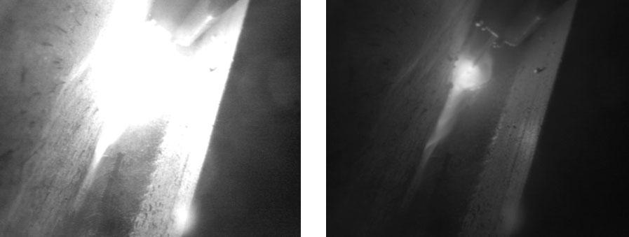
Attempts to capture open arc welds (GMAW, GTAW, laser, plasma) using standard cameras have taken many forms over the years, from looking at the weld through paper, to capturing the basic nature of the movement and “look” of the arc, to using filters to darken the arc somewhat to capture it in more detail. But much of the information is inevitably lost with such techniques. For instance, using an optical filter in front of the camera can lower the brightness of the arc and that of the background, making it very difficult to see the details around the weld arc such as the weld bead and substrate. As it may not be possible to remove such types of filters easily when there is no arc, the resulting weld area images when no arc is present end up being almost completely dark. While special filters such as LCDs or photochromic filters are possible solutions that can be switched from a “weld” mode to a “no-weld” mode on a camera, the dynamic range available with LCD filters and a photochromic filter’s speed of change make them less than ideal for use when imaging the weld area as the weld goes on and off.
The introduction of high-dynamic-range (HDR) imaging has changed the landscape of how welding can be imaged.
HDR has been used in photography for some time now. For example, most cell phones today have an HDR option on their camera, where multiple exposures of a picture are taken and mathematically combined to get the best possible contrast in the image. But that is in the service of creating just one still image on a consumer device. The task becomes more complex when creating a video, especially when taking into consideration the brightness of a weld arc, which can be 10 million times brighter than its surrounding darker background. This is a far greater brightness range than the eye can see, and even more than what a typical camera can see.
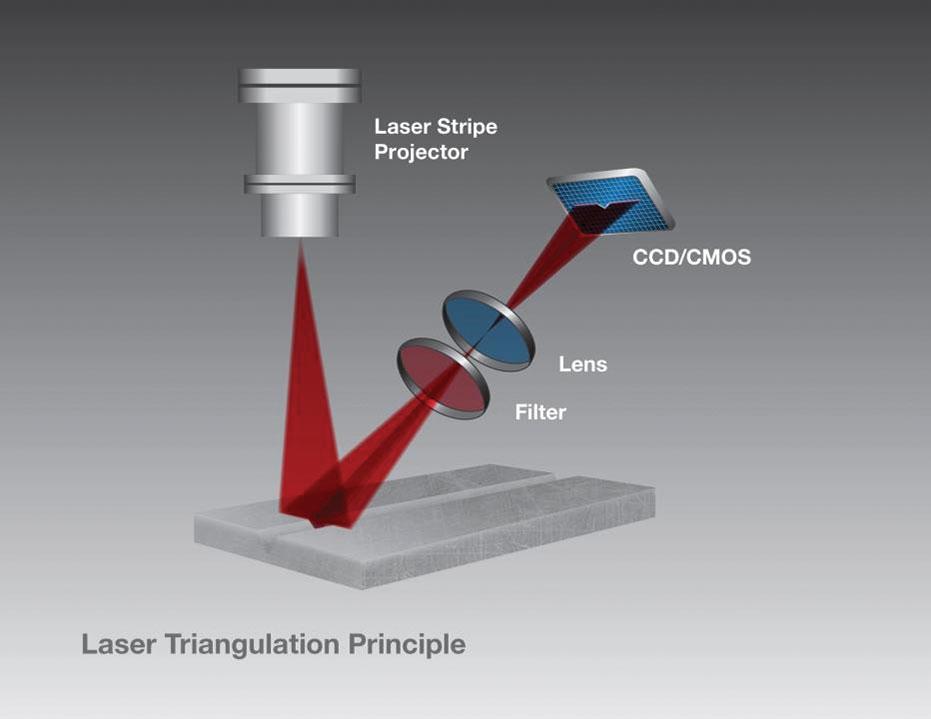
Figure 1 demonstrates the laser triangulation principle. Image: Xiris
Cameras with HDR sensors are now available to manage this. Such logarithmic sensors allow the HDR to be “baked into” the sensor itself by providing a natural logarithmic response that does not saturate with increasing light. The pixels on these sensors deliver a voltage output proportional to the logarithm of the illumination that strikes the chip, generating a response with dynamic range that is greater than 140 dB to produce a true HDR image. The resulting image can provide the user with a clear view of both the very bright light of the weld arc as well as the darker areas around the weld.
In Figure 2, the left side shows how a traditional camera with a linear response would respond to light, and the right side shows how a camera with a logarithmic sensor would respond. In both cases, the horizontal axis represents the amount of light that's coming into the sensor, and the vertical axis represents the voltage level that is generated by the sensor. For a typical linear sensor, as light levels increase from zero, there is a fairly linear response with the amount of voltage that is generated. But at a certain point the image gets saturated, so no matter how much more light is added to the sensor, the same voltage is emitted. That's why using a regular camera to capture a weld image results in a big white blob on the screen.
A camera equipped with a logarithmic sensor will respond differently. Even as the amount of light hitting the sensor is increased, there is an increasing amount of voltage that is emitted. Although the slope of the curve changes because the response is logarithmic, there still is an increase in the voltage output, providing detail of the image’s brightest features. As seen in the logarithmic curve in Figure 1, there is still a difference in voltage output between light levels at 90 and at 70, for example.
The results are shown in Figure 3. The image from a linear sensor with heavy saturation makes it difficult to see where the arc is in the image. However, the image from a logarithmic camera shows detail of the weld arc itself and the darker background, including the weld bead, seam, and the torch.
Displaying such images for viewing requires converting the sensor signal from analogue to digital, then applying a software process called tone mapping that remaps the image down to 8-bit images so that they can be viewed using a traditional monitor in the most pleasing image for the viewer.
Weld cameras of this kind can be used for monitoring all types of open-arc welding processes by anyone involved with welding, such as end users, machine builders, or research labs. Special ruggedized systems are available for harsher environments such as high-current GMAW, GTAW, or SAW processes where high power, temperature, fumes, and restricted available space present a challenge for implementing a camera.
Most weld camera systems are available as monochrome or colour systems. The use of colour provides more levels of hue that can be appealing for the user in certain applications.
The main items that can be monitored with such a camera include the weld arc, the melt pool size and shape, the stick-out length of the wire, and the alignment of the torch to the seam. The shape of the weld bead also can be interesting to see as it may affect the outcome of the weld process. After determining what a good weld looks like for a certain process, operators can then monitor all the elements of the weld to see if any of the features move or change size and therefore get out of control.
For many, the data available in the visible light range that these cameras handle—between 400 and 750 nm—is sufficient.
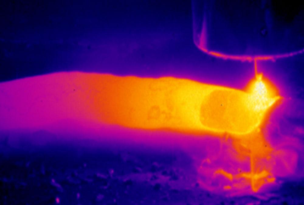
For those who require data from outside of this range, thermal cameras are an interesting option. These cameras can also be HDR, but they operate at a different wavelength, from about 900 up to 1,700 nm, in the short-wave infrared (SWIR) band.
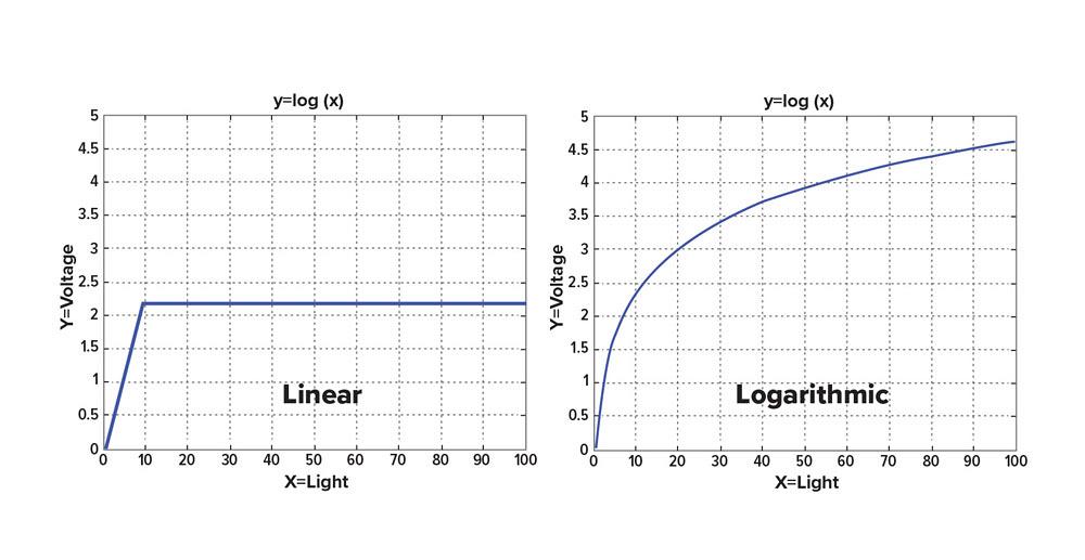
Figure 2: The two graphs show the voltage output of linear and logarithmic image sensors. Image: Xiris
The benefit of using SWIR imaging for welding is that it is the best range to measure and monitor hot metal from 350 to 1,800 degrees C. In a typical welding process, the melt pool is cooler than the weld arc but hotter than the background. Therefore, thermal camera images can easily segment these different regions based on their temperature. This can be very useful for fabrication shops using advanced welding processes and controls that want to control the power of a welding source and observe the size and shape of the resulting melt pool (see Figure 4).
Thermal cameras can be calibrated precisely so that the temperature of each pixel on the screen can represent the temperature of the object in the image. By monitoring the various components in a weld area, it’s possible to see how fast the weld bead is cooling or understand the profile of the cooling (whether it is cooling symmetrically, for example). If the cooling takes too long, the resulting bead may become too ductile; if it cools too fast, it may be too brittle. For multi-layered welding processes such as cladding or additive manufacturing, making sure that the previous layer of deposited material is cooled properly ahead of adding another layer can be critical as well. Using a thermal camera to measure the previously deposited temperatures can help determine the ideal weld deposition rates for such processes.
Cameras can provide images and data for the control and quality assurance of welding processes. The key to maximizing the value of the best camera hardware, however, is to have the right software technology that allows fabricators to extract information from the images of the weld and make a decision. The combination of the two provides the full value to the fabricator.
When looking for a camera system, consider the software package that goes with it, ensuring it meets the robustness of the cameras and the process requirements.
Weld monitoring with cameras is essential for today’s competitive environment to provide quality assurance. The right technology will not only provide the data required, but it also creates a safer and more efficient work environment for welding operators.
Cameron Serles is founder and president of Xiris Automation Inc., 5046 Mainway Unit 2, Burlington, ON L7L 5Z1, 905-331-6660, xiris.com.


Keep up to date with the latest news, events, and technology for all things metal from our pair of monthly magazines written specifically for Canadian manufacturers!
Start Your Free Subscription
Easily access valuable industry resources now with full access to the digital edition of Canadian Metalworking.

Easily access valuable industry resources now with full access to the digital edition of Canadian Fabricating & Welding.